Yonder Robotics · 2024–2026
Systems & Architecture
Owning the CAD library means owning the decisions nobody photographs. This is the layer underneath the arm and the chassis: how the machine is broken into assemblies, where its mass actually goes, and how power and signal get to the far end of a six-DOF arm.
One assembly tree
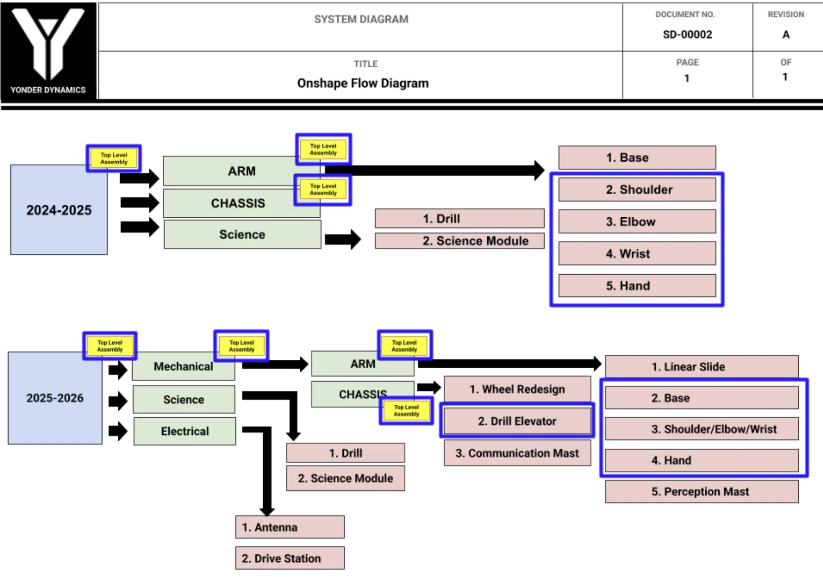
A released system diagram fixes what the top-level assembly contains and what each sub-assembly owns: arm into base, shoulder, elbow, wrist and hand; chassis into drive and structure; science into drill and sample module. Two seasons sit side by side on the same sheet, so what changed between them is legible at a glance rather than buried in revision history.
The point is not the diagram. It is that a team of rotating undergraduates can open the CAD and find things where the diagram says they are.
 01
01Weight budget
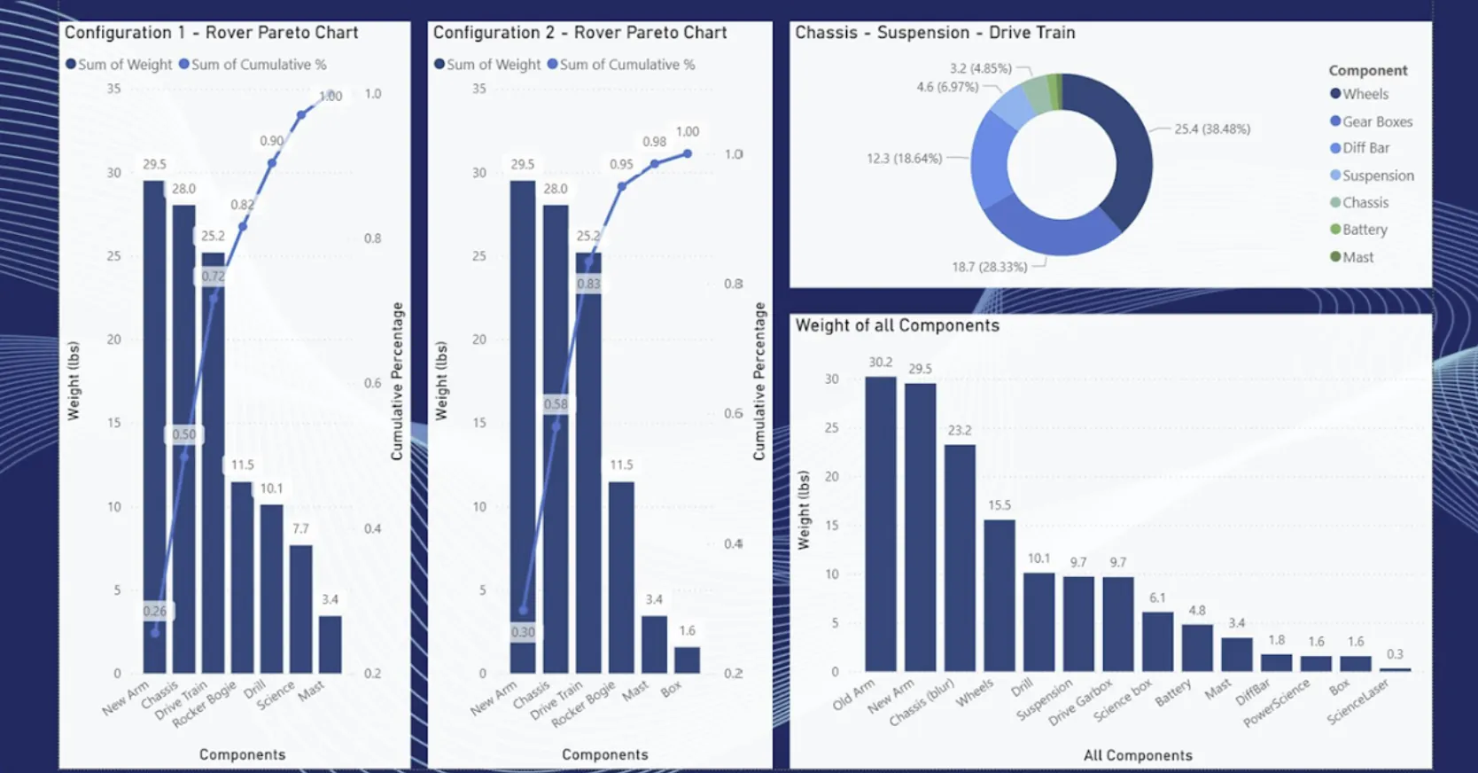
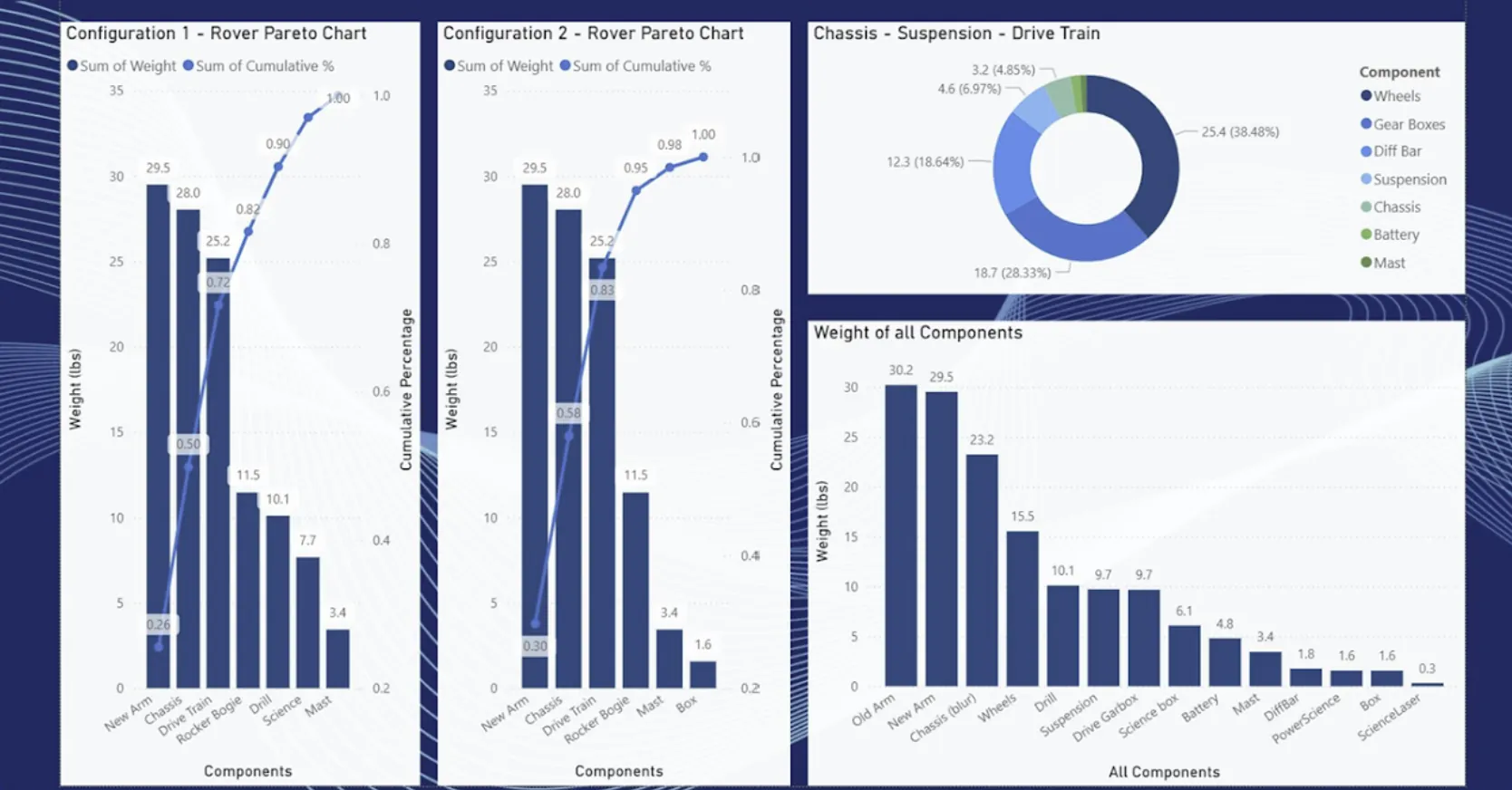
Component mass ranked as a Pareto across competing rover configurations: per-component weight against cumulative percentage, with the subsystem split beside it. A handful of parts carry most of the mass, and the chart is what makes that arguable rather than felt.
Configuration choices got made against this, not against intuition about which bracket looked heavy.
 00
00Wiring architecture
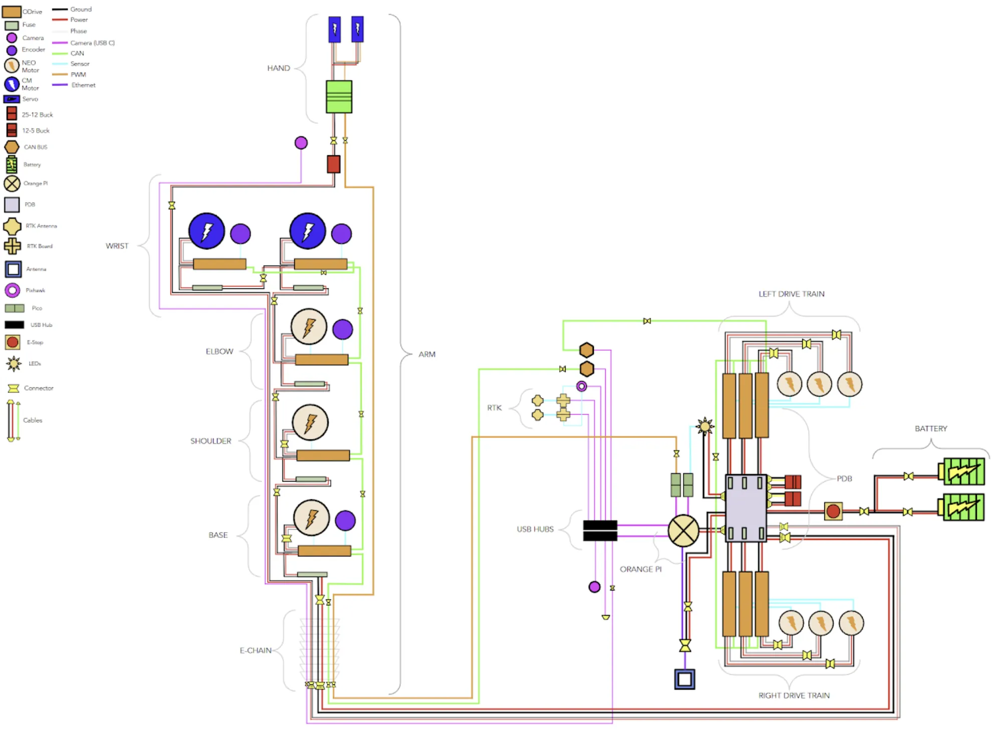
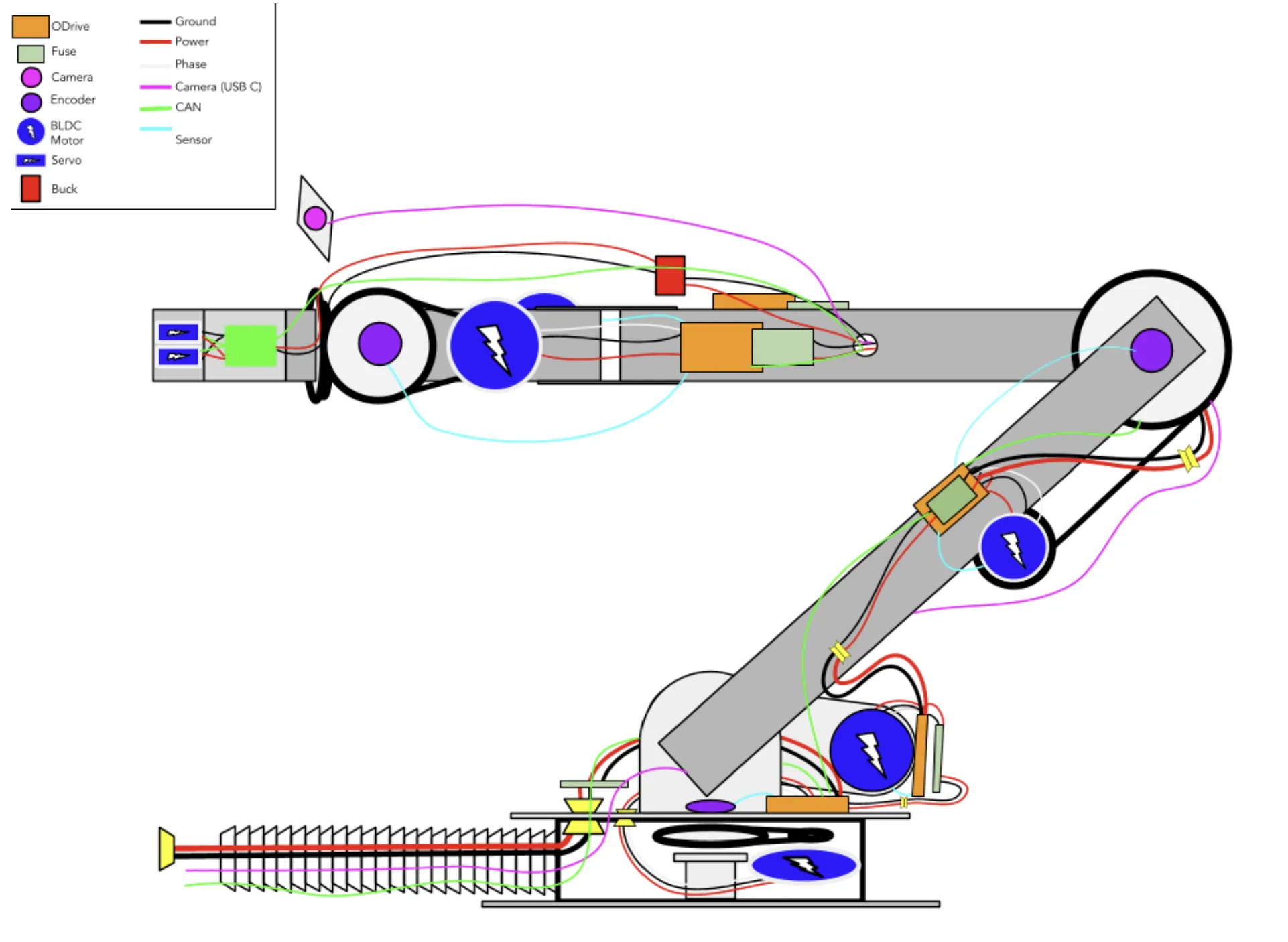
A whole-robot wiring diagram and a second drawing at arm level, both colour-coded by run type: power, ground, encoder, camera, and bus lines kept visually distinct so a harness can be traced without a multimeter.
Electrical is where a rover rebuild loses its week. Drawing it as architecture rather than as-built is what makes the harness reproducible next season.
Nonprofit