
Yonder Robotics · 2025
Differential Wrist
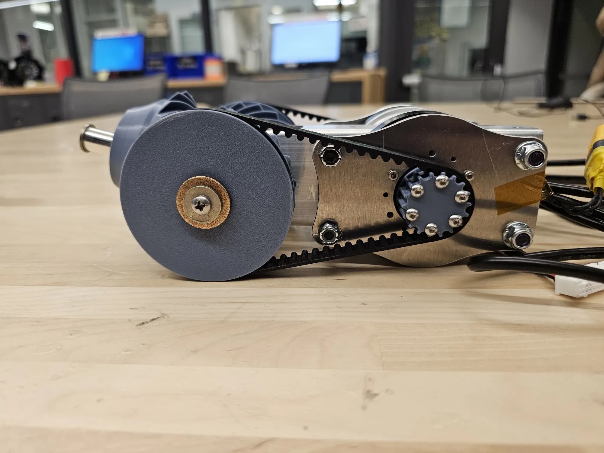
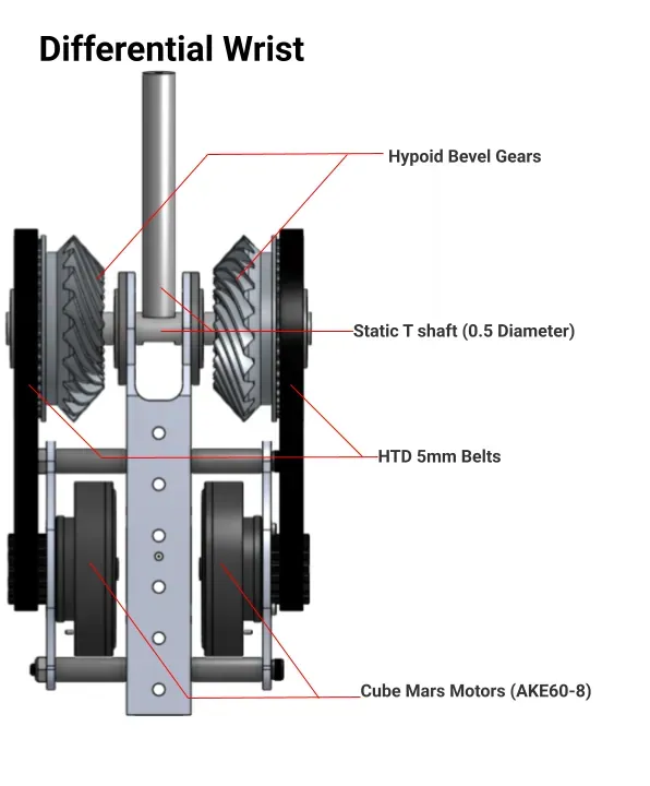
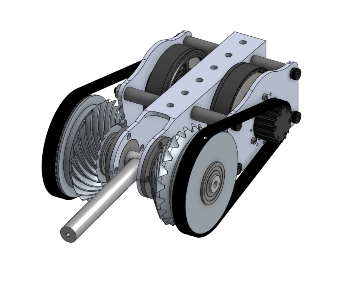
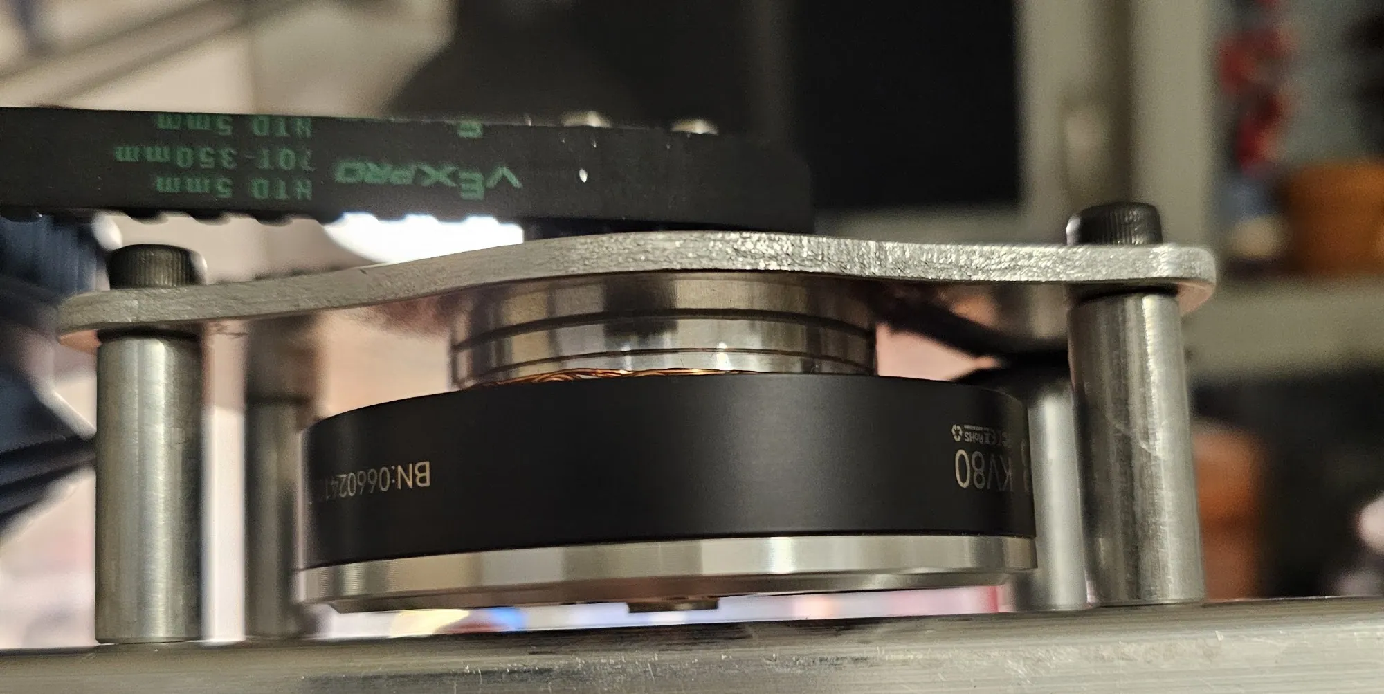
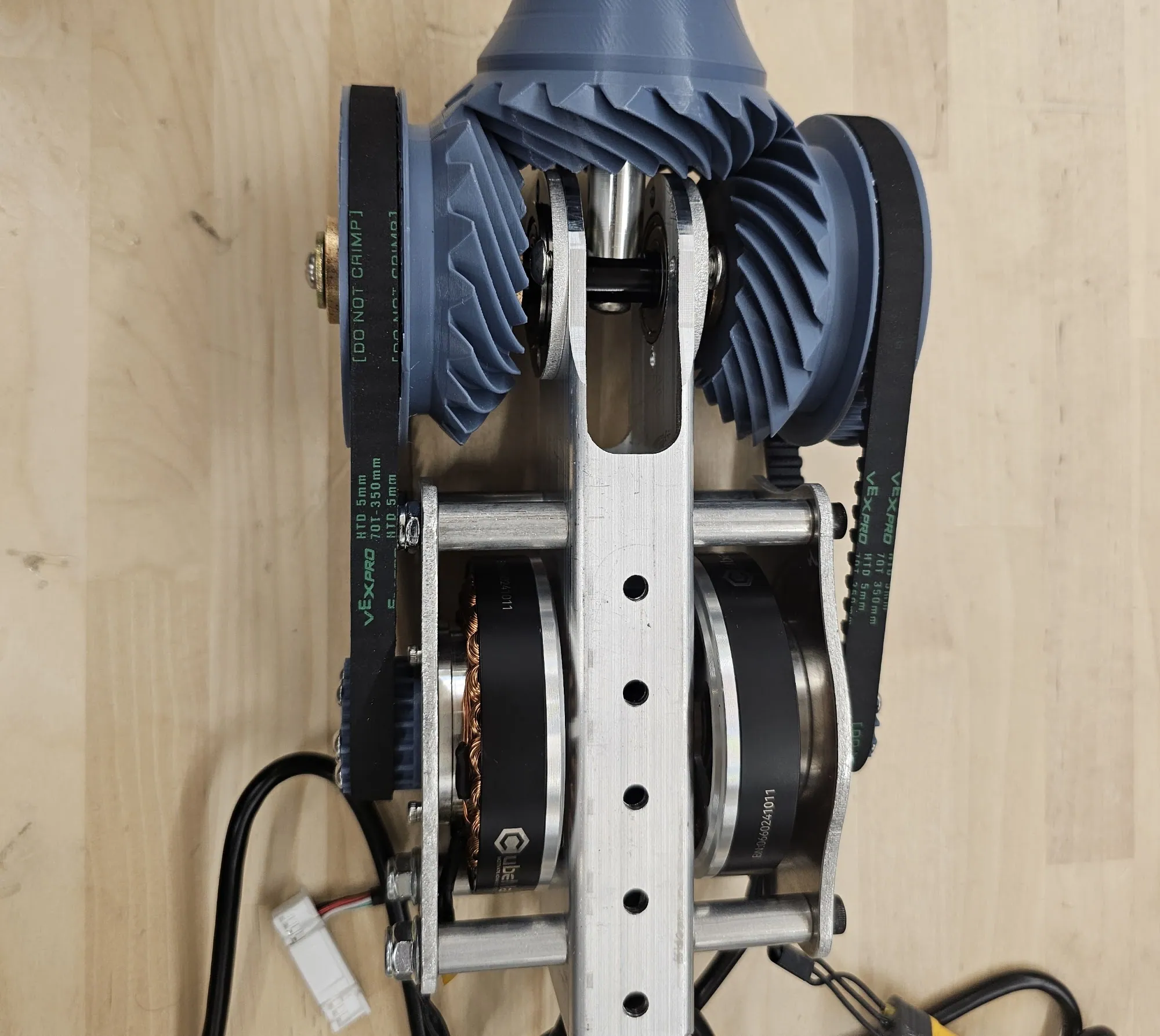
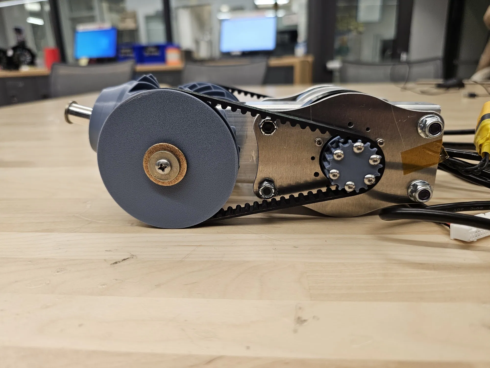
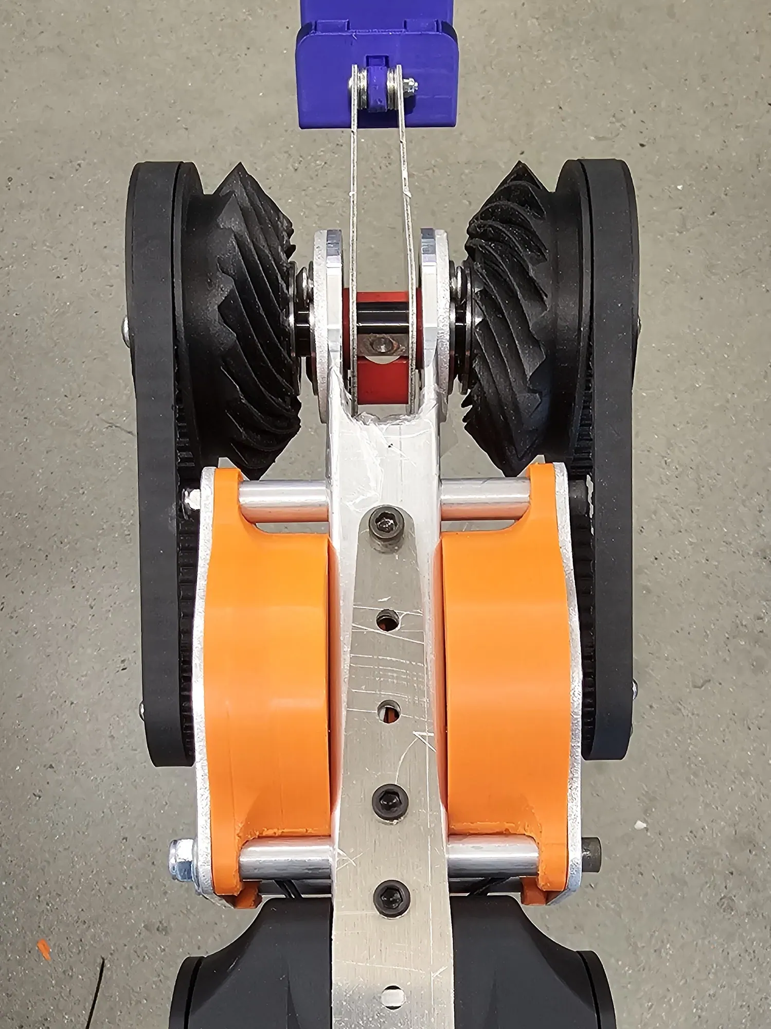
A compact dual-axis wrist giving the rover arm pitch and roll from two motors sharing a single dead axle. Two Cubemars AKE60-8 outrunners, 5 Nm continuous each, through 2:1 HTD belts into custom hypoid bevel gears.
The differential
The T-shaped dead axle is what makes it a differential rather than two stacked joints:
- Same direction, same speed → pitch.
- Opposite directions, or different speeds → roll.
Three iterations to get here
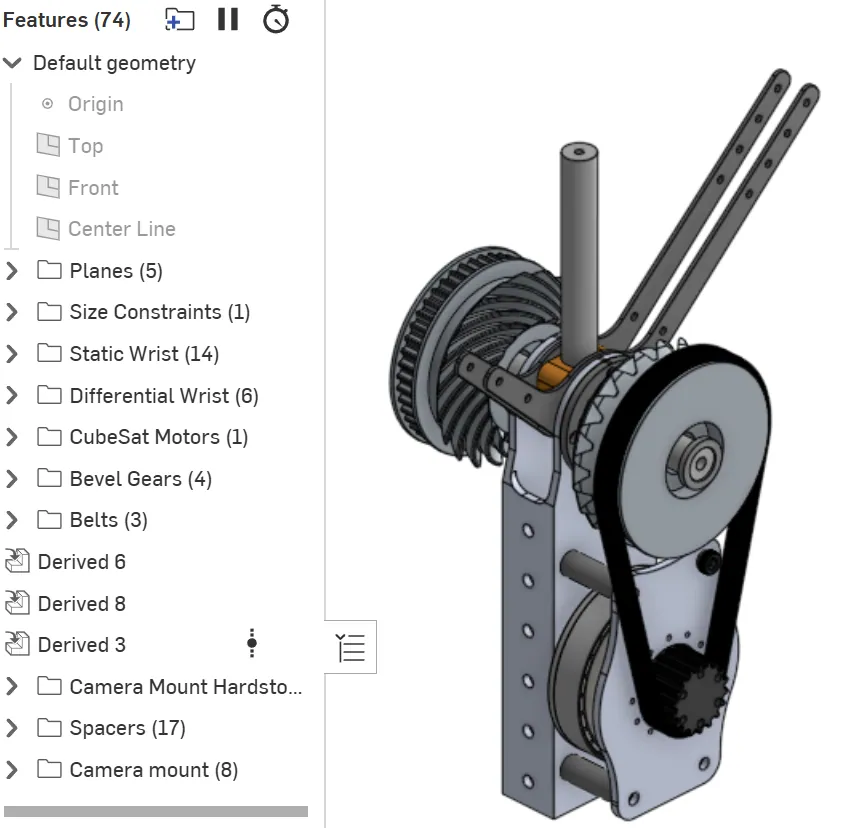
The final differential layout only emerged after three major virtual iterations, when the initial yaw-linkage design was scrapped outright. What replaced it had a different goal: a modular, self-contained wrist that could be removed and serviced without touching the rest of the rover.
 13
13Hypoid bevel gears
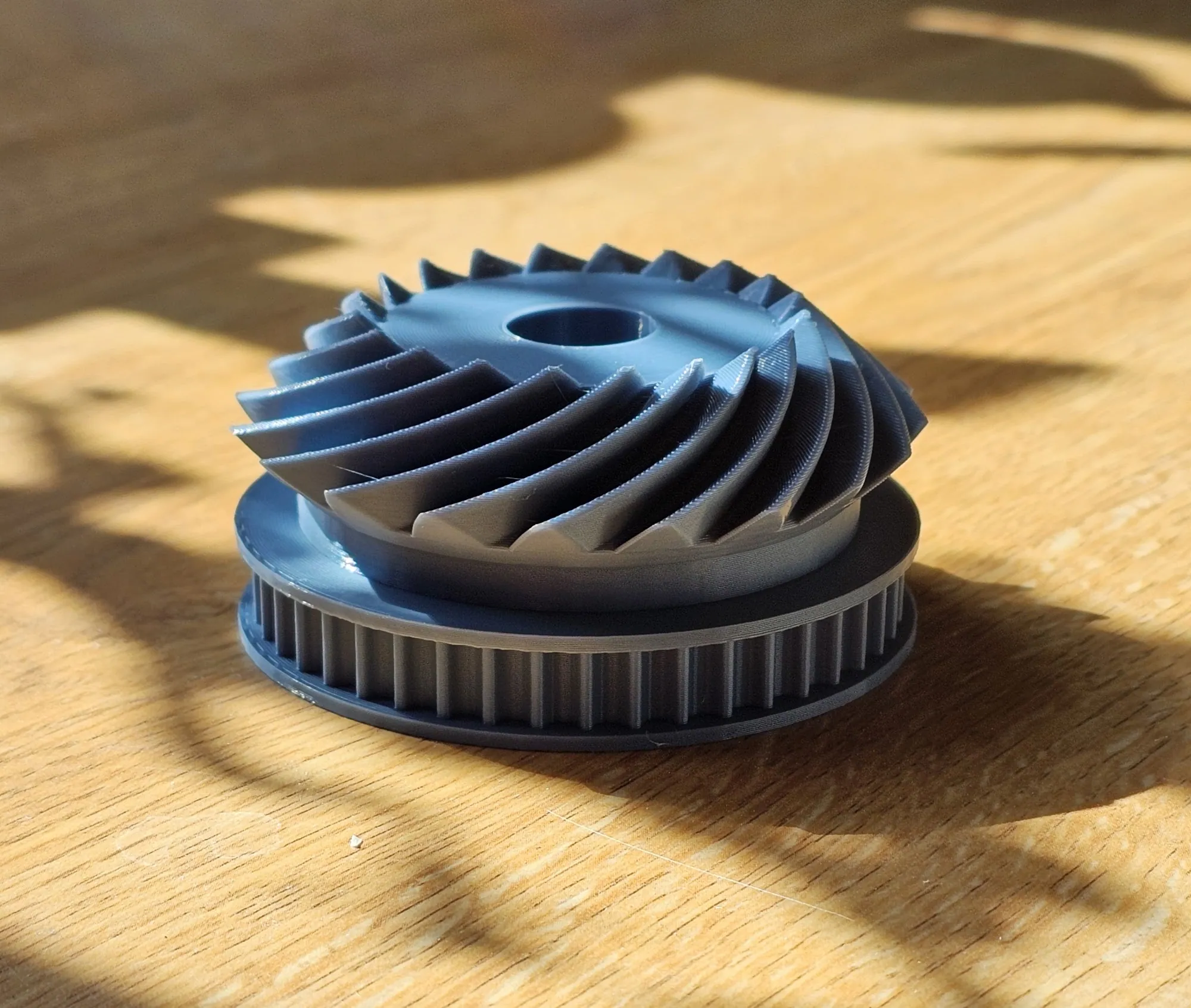
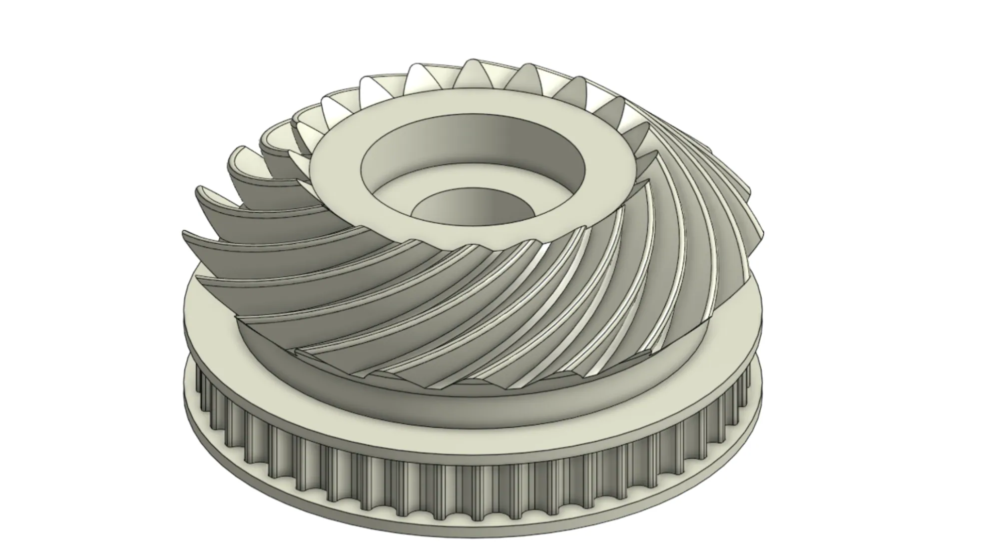
A standard bevel gear engages in one plane of contact. A hypoid maintains three, spreading load across a far broader surface, which matters disproportionately for printed parts, and extends gear life.
I designed the gears in Onshape with a custom FeatureScript for spiral geometry and offset control, then boolean-merged the hypoid form into a second FeatureScript generating the HTD 5 mm belt profile. Mesh alignment between pulley and gear body is guaranteed, and the part stays monolithic and printable.
MATLAB validation
Contact and bending stress from standard AGMA equations, accounting for dynamic loading, material, load distribution, and geometry. Size correction, crown, curvature, and reliability factors all included and kept conservative; spiral bevel geometry factors approximated from AGMA charts.
Result: safety factor 3.0. That is what justified moving from PLA prototypes to CF-Nylon production parts.
Manufacturing
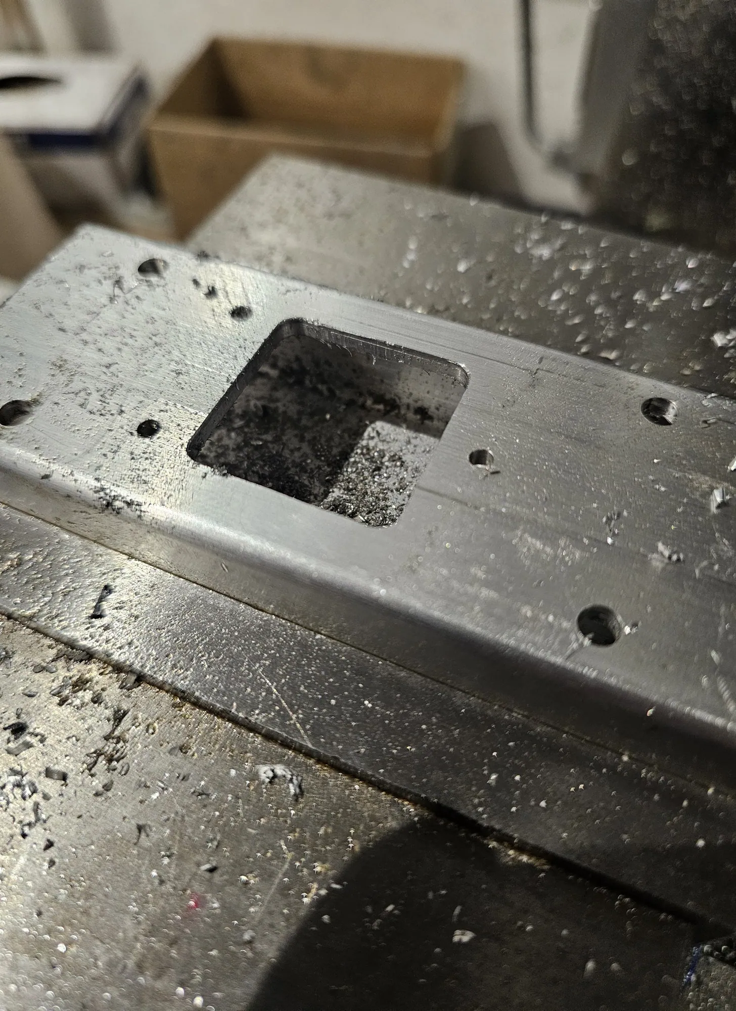
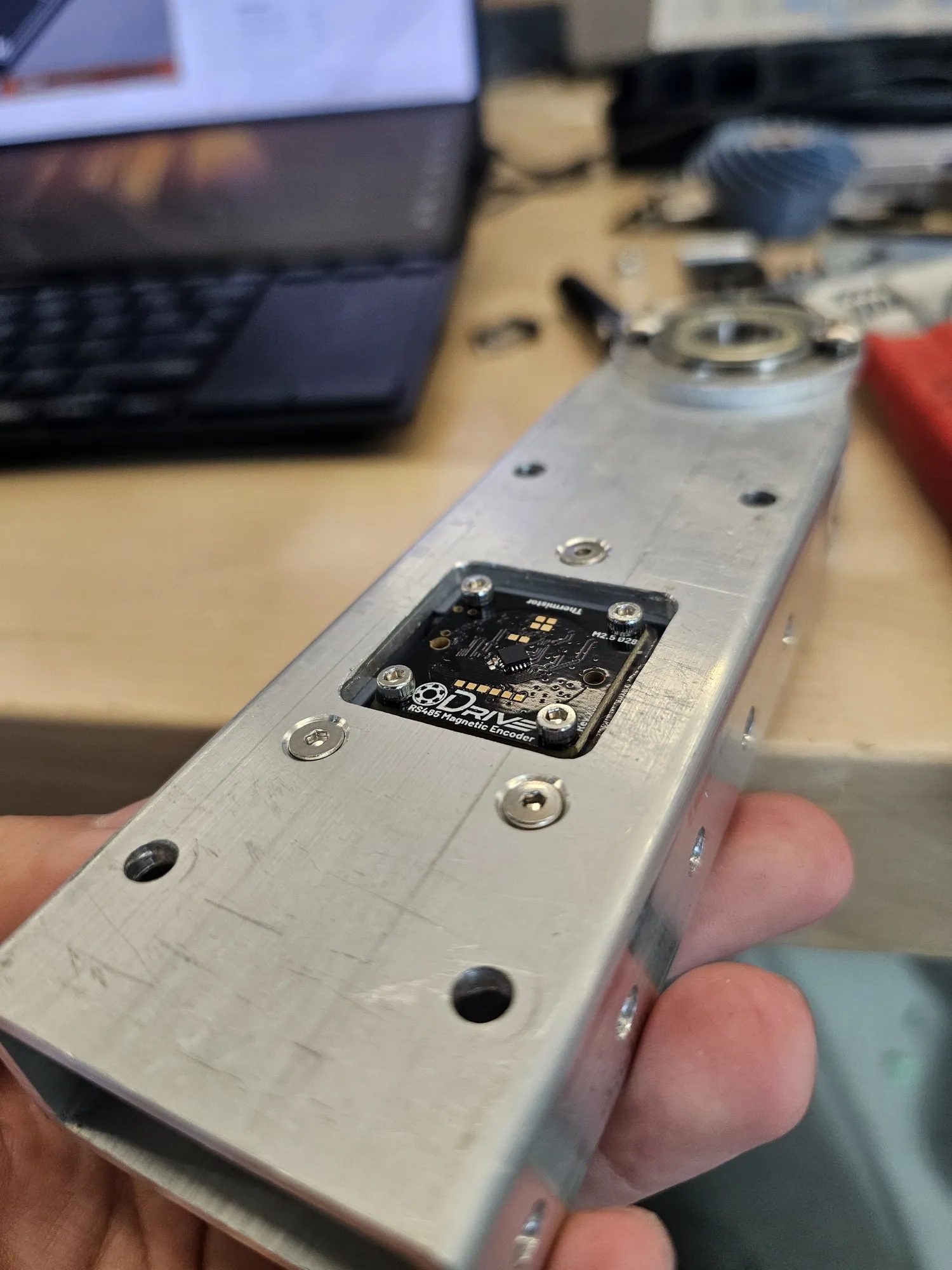
Tube stock holes and cutouts manually milled; curved features CNC milled with tool paths from Autodesk Fusion. Motor plates laser cut from 1/8" aluminum. The T-shaft is two 0.5" shafts lathed, tapped, and milled flat to join.
Gears and pulleys printed in tough PLA for prototyping, CF-Nylon on a Markforged for production.
Assembly
Standard M3 and M4 fasteners and 0.5" ID bearings throughout. Each bevel gear rides on two bearings so it spins free on the shaft; the main structure uses two more to constrain the shaft itself. Motors fasten to the plates with M3 screws, the pinion pulley bolts to the motor, and the HTD 5 mm belts go on last.
Motor plates sit on 1.1" standoffs, the spacing that sets belt tension and keeps the two drives from interfering.
Gallery
Wrist assembled
Printed PLA gears first, CF-Nylon for the parts that ran.
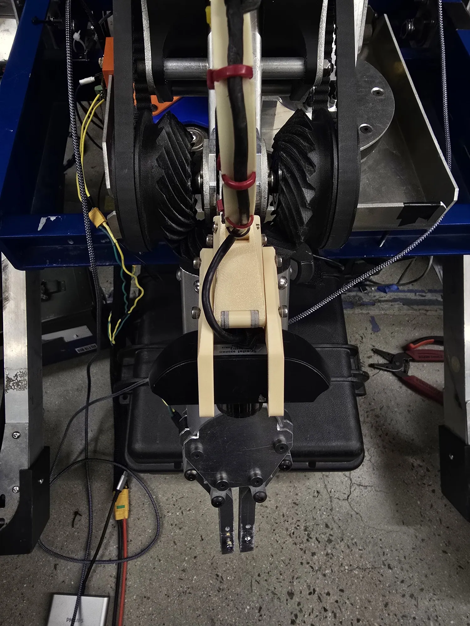
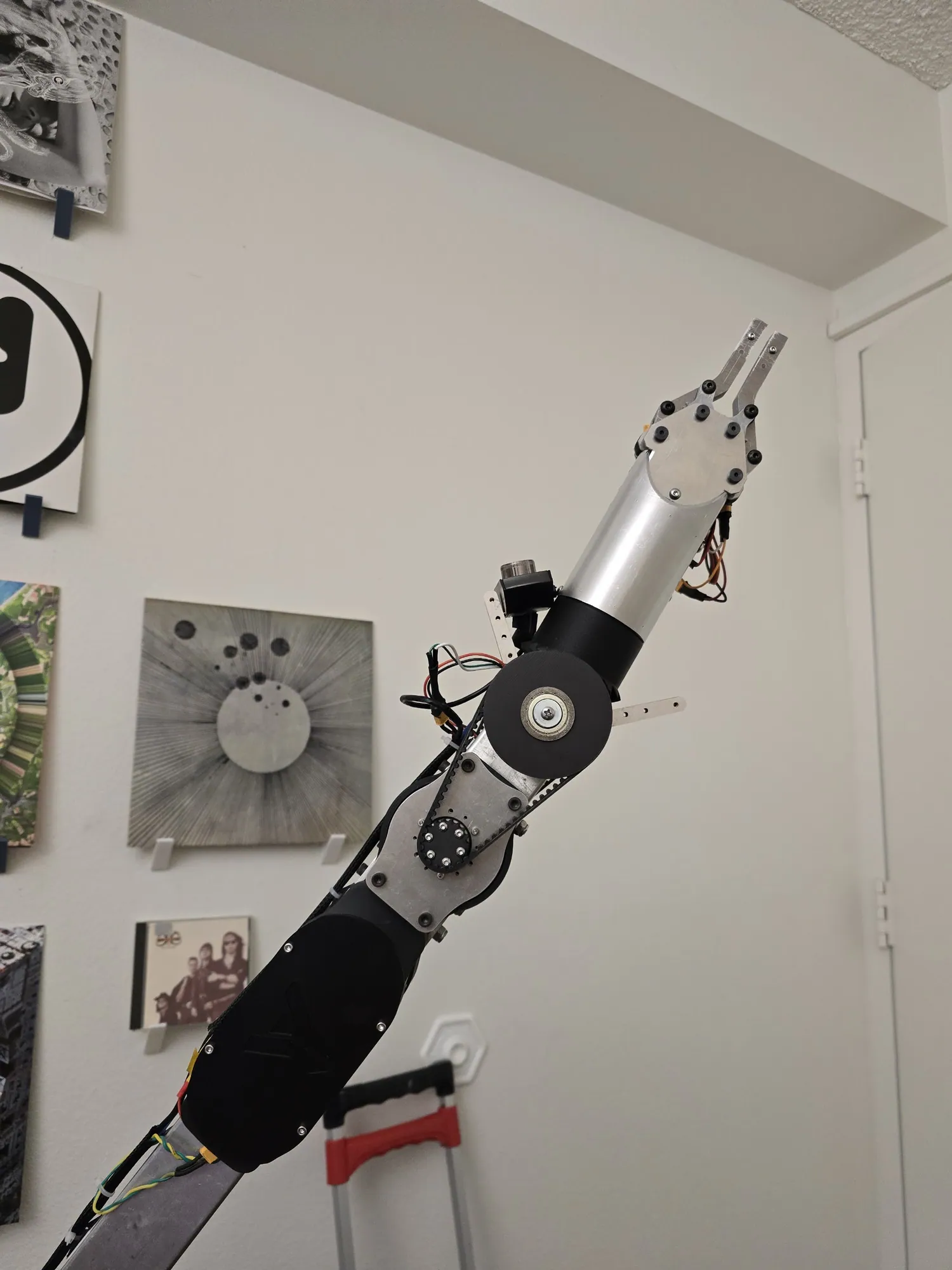
On the rover
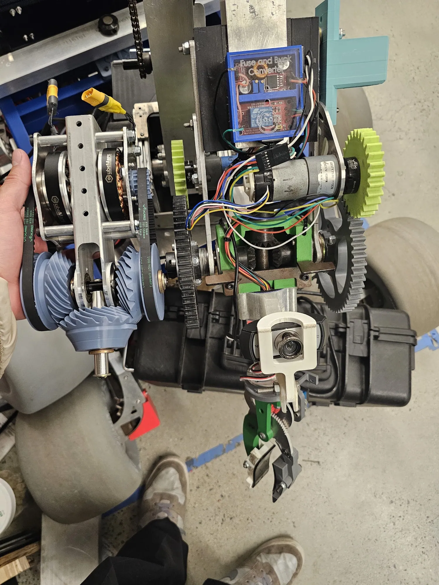
Mounted behind the hand, at the end of the forearm.
Yonder Robotics