
Yonder Robotics · 2026
ARM 3.0
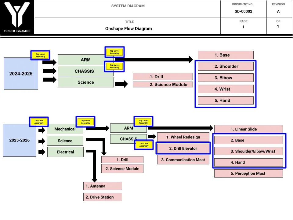
A 6-axis arm (linear slide, rotating base, shoulder, elbow, wrist pitch, and wrist roll) for UC San Diego's University Rover Challenge entry. I led it end to end: initialized the project, set the design requirements, developed the motor module architecture and the core concepts for the base, shoulder, elbow, and wrist pitch, and oversaw the remaining components.
The arm, part by part
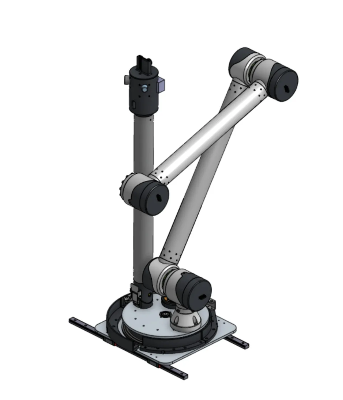
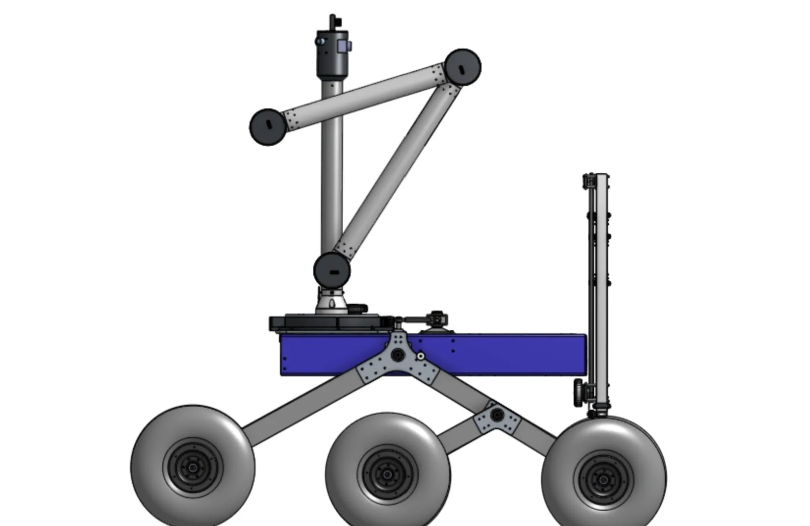
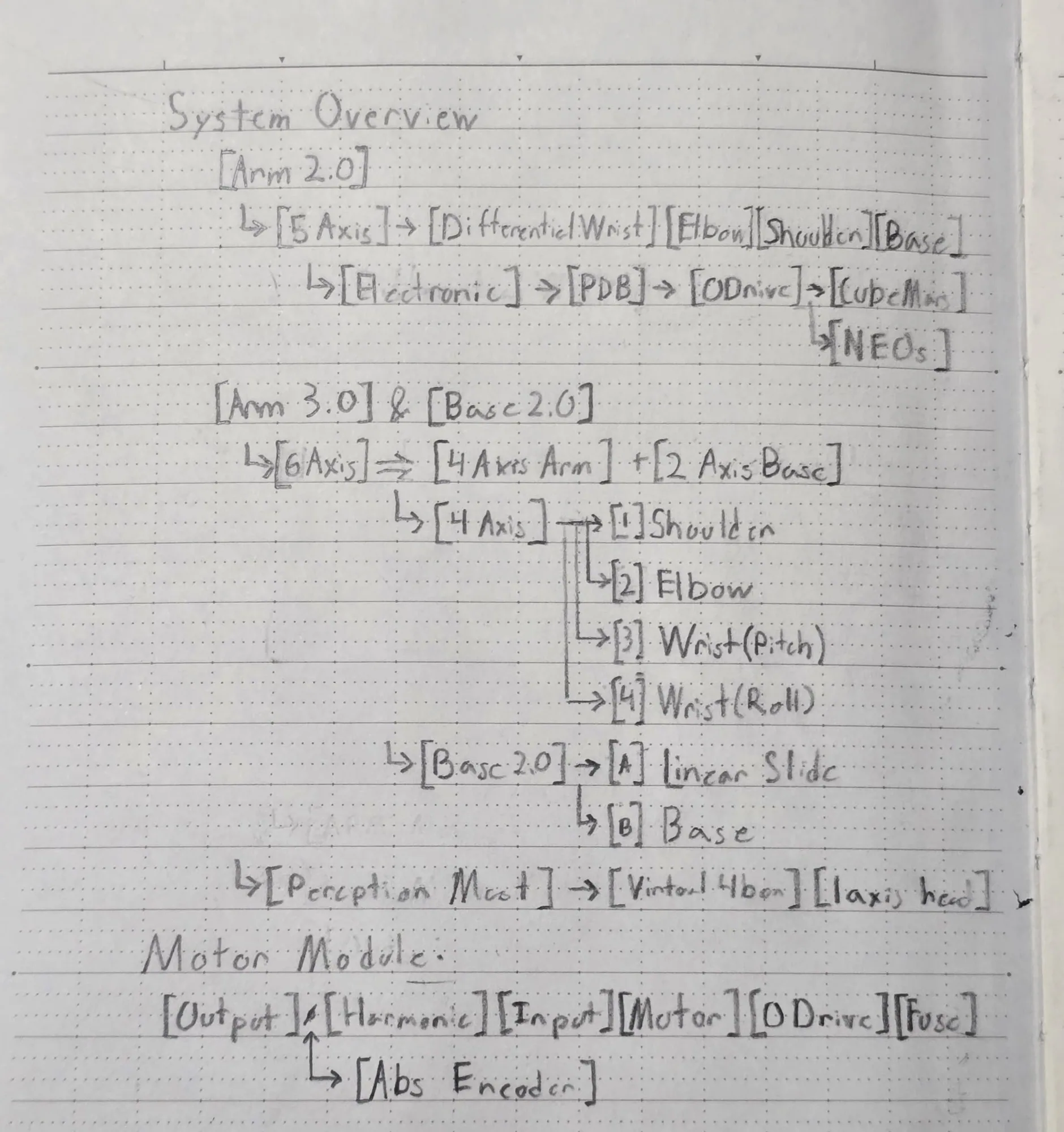
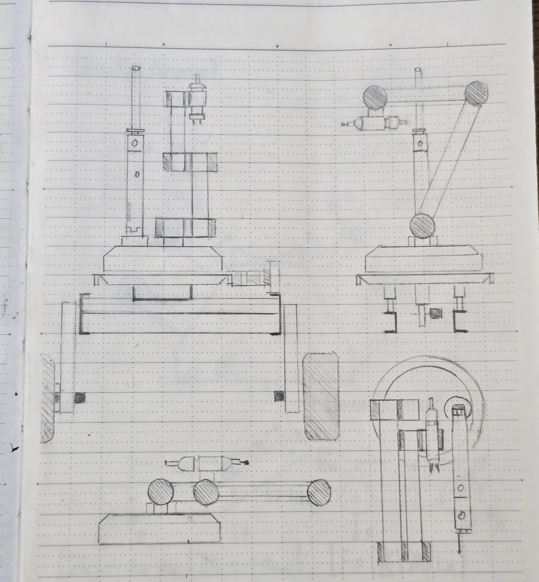
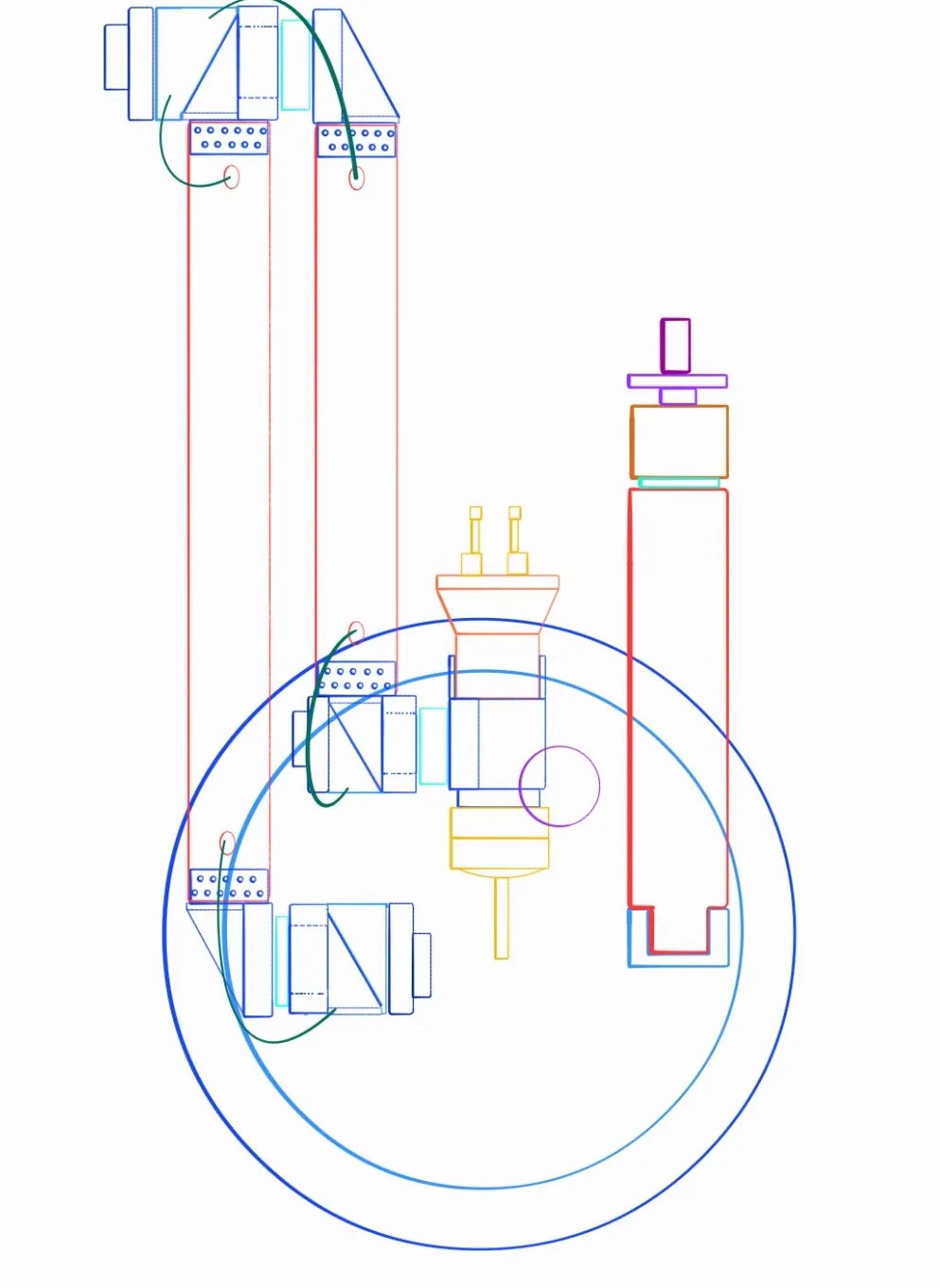
ARM 3.0 is a 6-axis manipulator carrying 5 kg at a 2.5 factor of safety. The axes split into a 4-axis arm (shoulder, elbow, wrist pitch, wrist roll) riding on a 2-axis base of linear slide plus rotating turntable, with a perception mast developed alongside it.
I initialized the project, defined the design requirements, developed the motor module architecture and the core concepts for the rotating base, shoulder, elbow, and wrist pitch, and oversaw the components I did not draw myself.
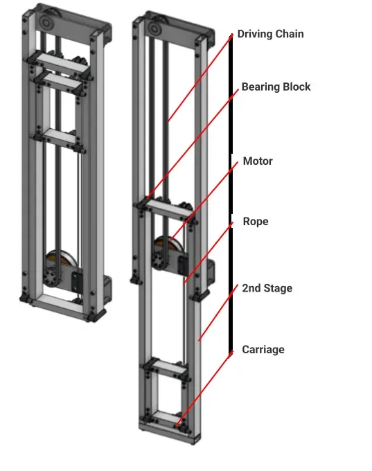
- Linear slide: chain-driven two-stage carriage that raises the whole arm instead of asking the shoulder to reach for height.
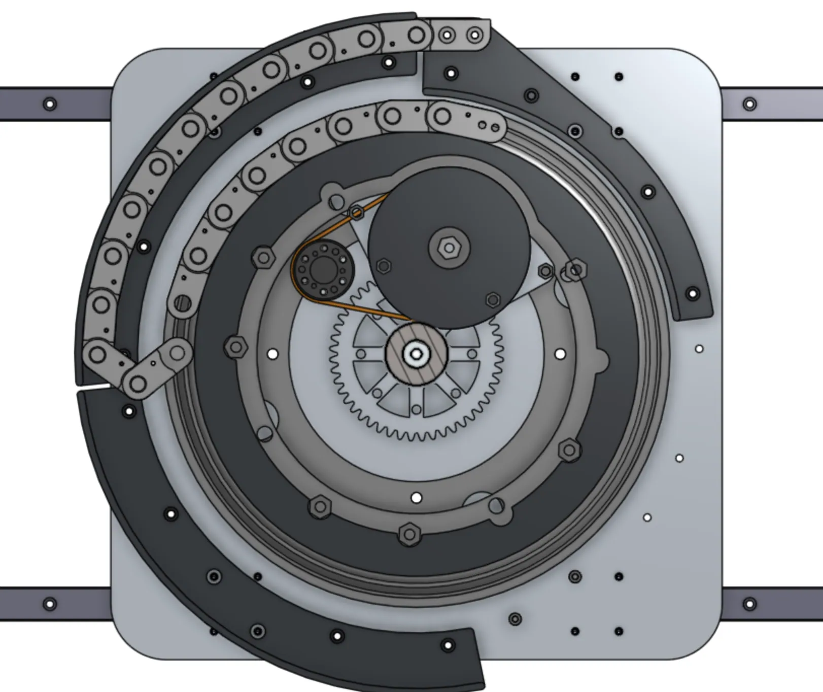
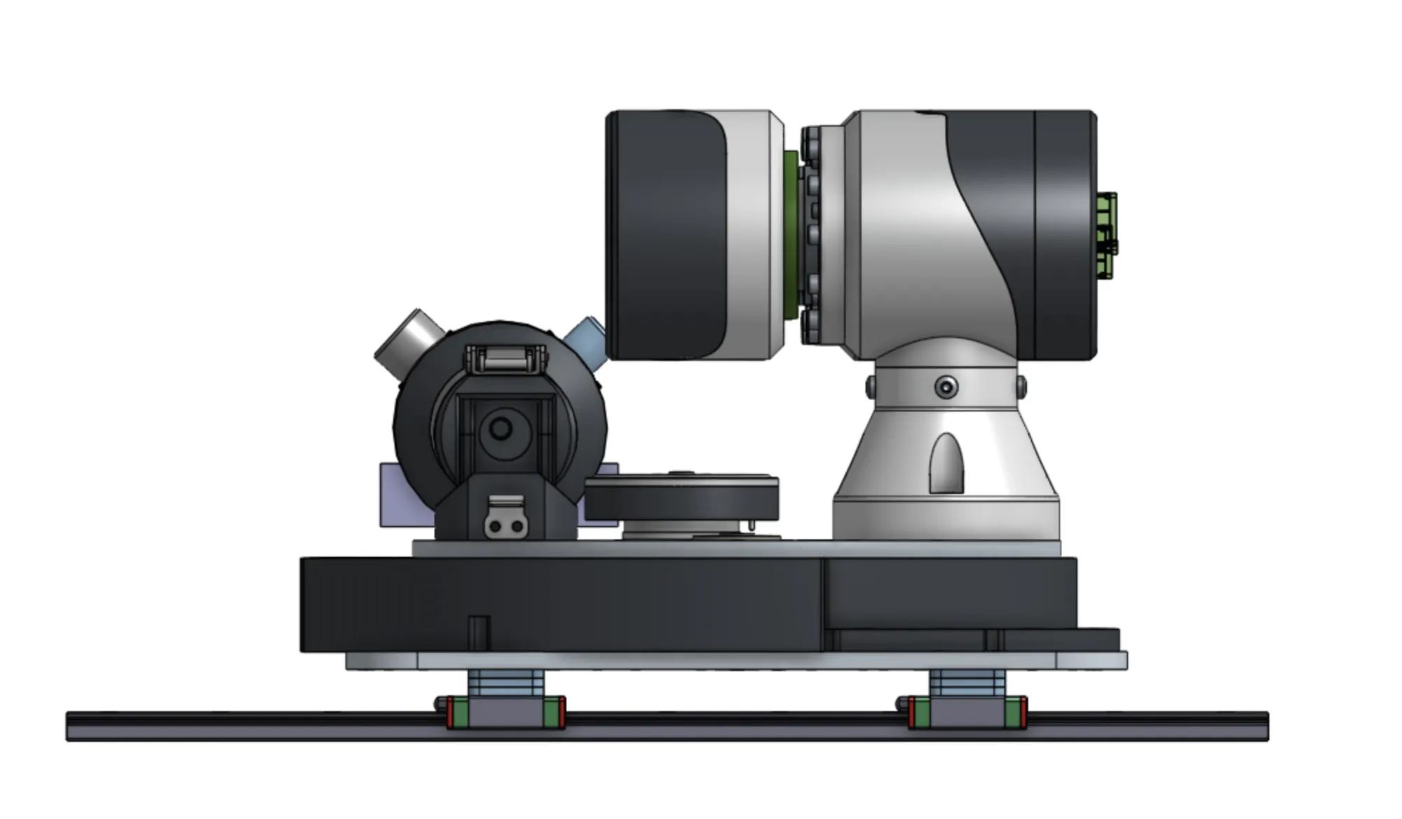
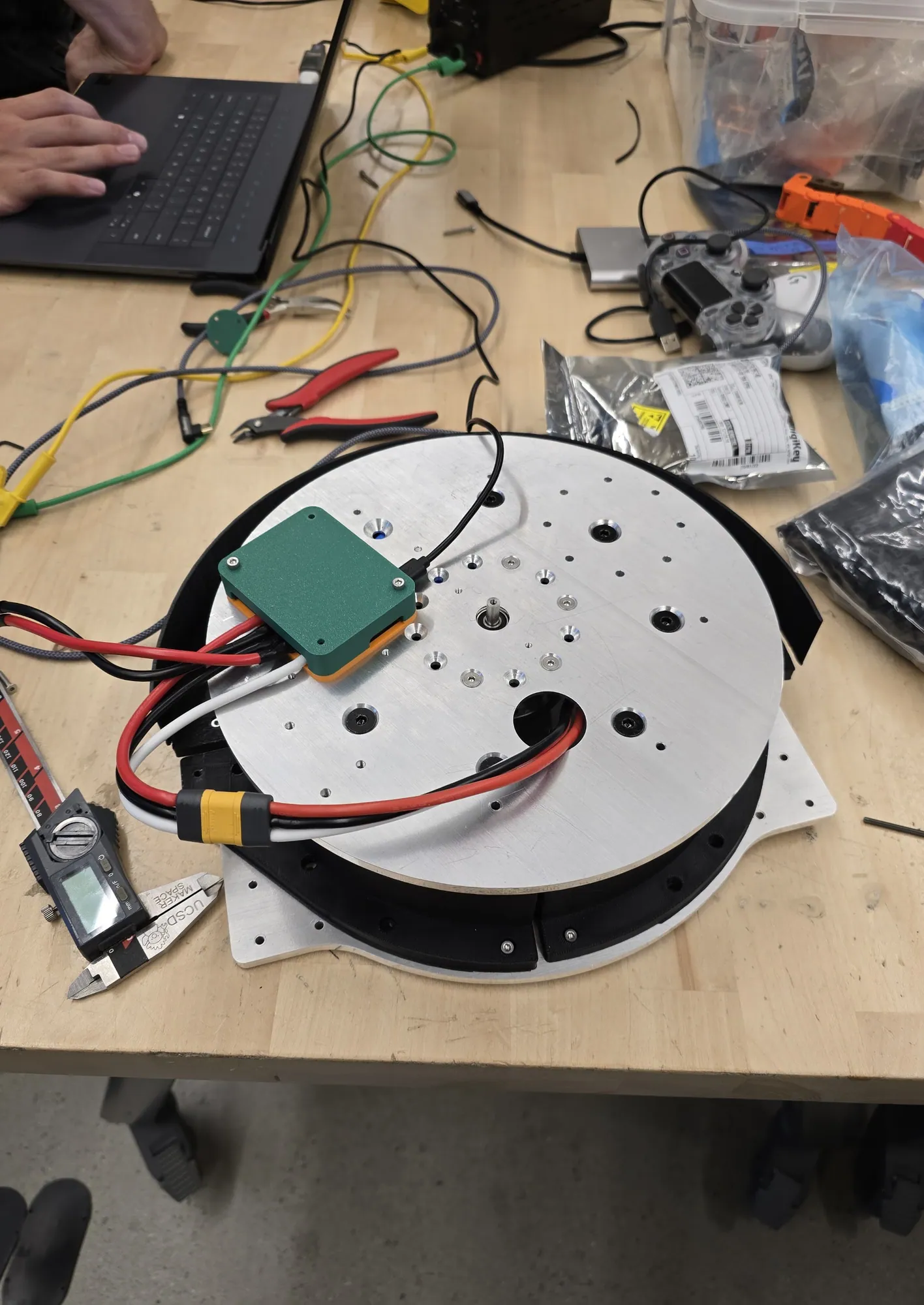
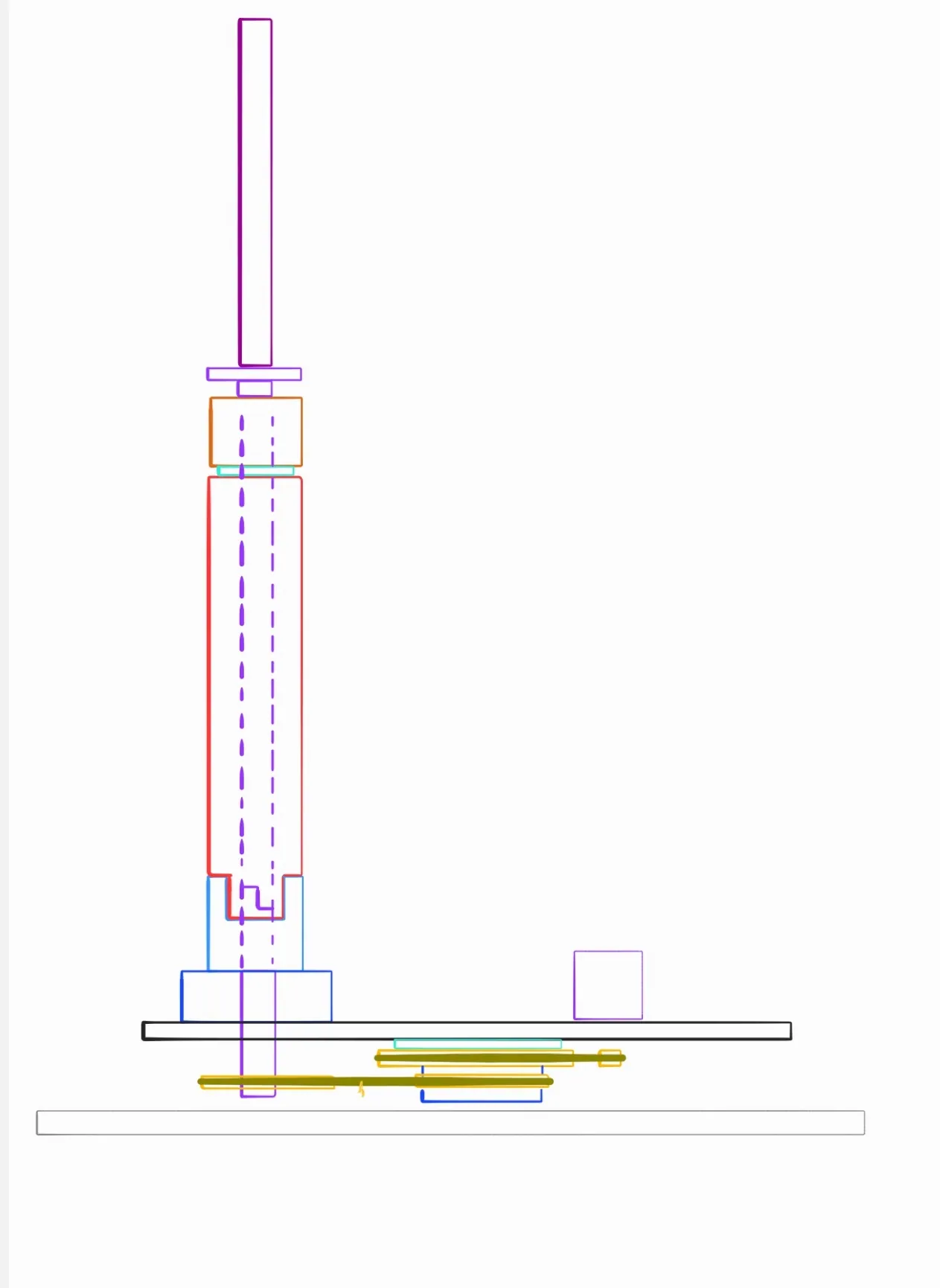
- Rotating base: a COTS turntable bearing preloaded on a 0.5 in dead centre shaft, driven by a CM-AKE60 through 6.75:1 compound reduction for 34 Nm, with a custom E-Chain for continuous 360°.
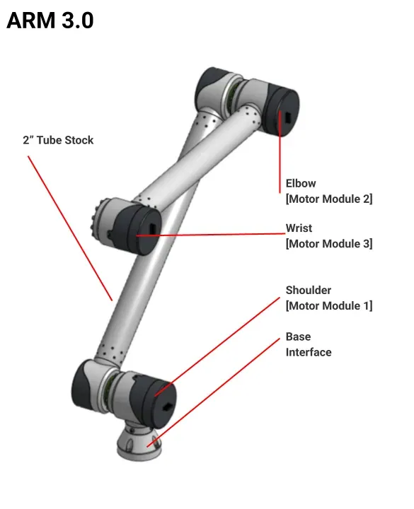
- Shoulder: motor module 1, 200 Nm.
- Elbow: motor module 2, 120 Nm.
- Wrist pitch: motor module 3, 50 Nm. Wrist roll is still in development.
- Links: 2 in OD 6061 tube between the modules, 1/8 in wall on the lower link and 1/16 in on the upper, removable from the joints.
- Perception mast: a stable camera reference frame for the automation and simulation stack.
![ARM 3.0: perception mast, elbow [module 2], wrist [module 3], shoulder [module 1], base, linear slide](/img/arm-3-0/32.webp)
One module, three scales
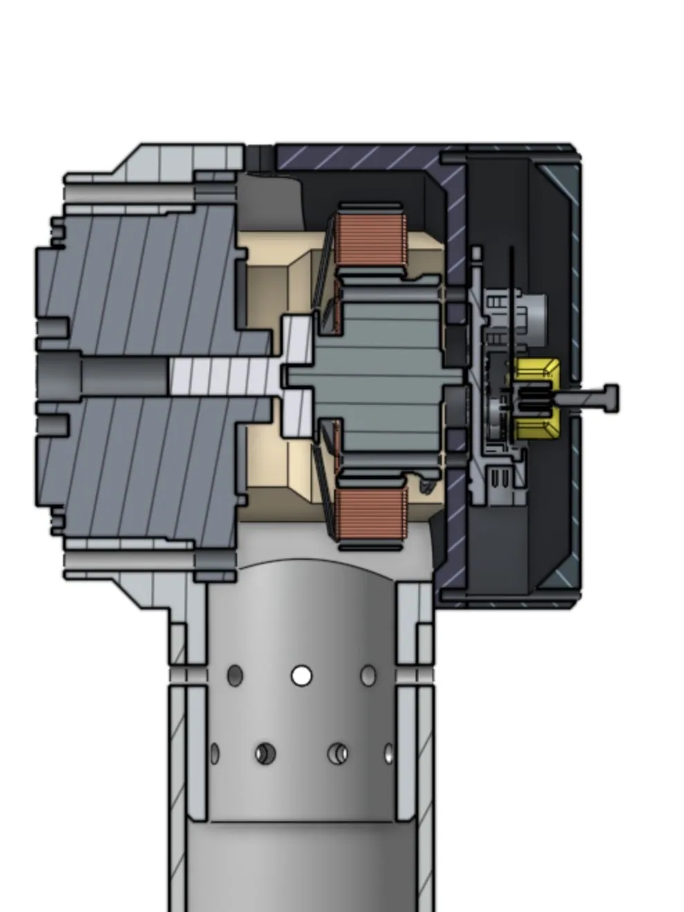
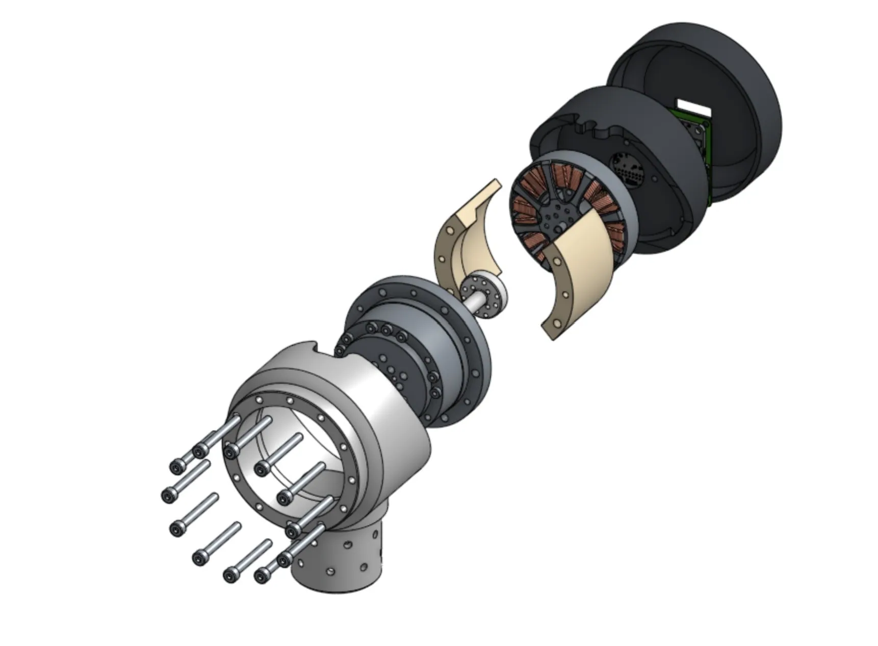
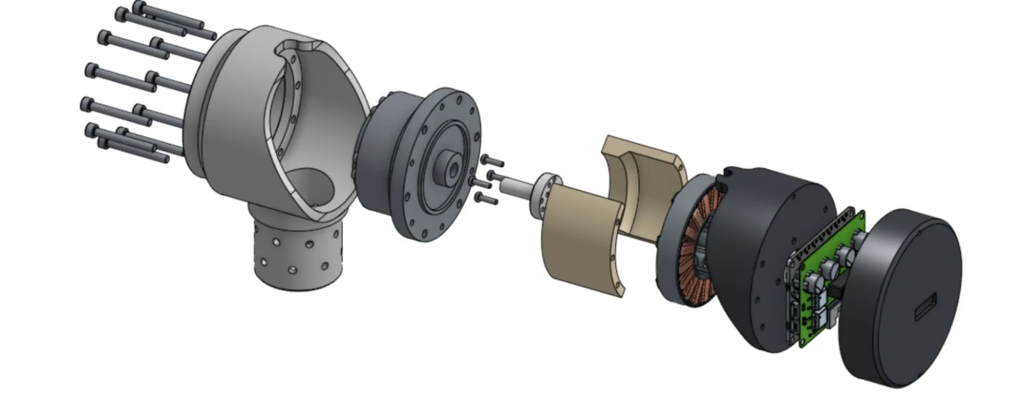
Shoulder, elbow, and wrist pitch are mechanically the same module. Each is built around a Harmonic Drive 17-100-118879-11 at 100:1 and differs only in which T-Motor brushless outrunner is fitted to meet the torque: 200 Nm at the shoulder, 120 at the elbow, 50 at the wrist.
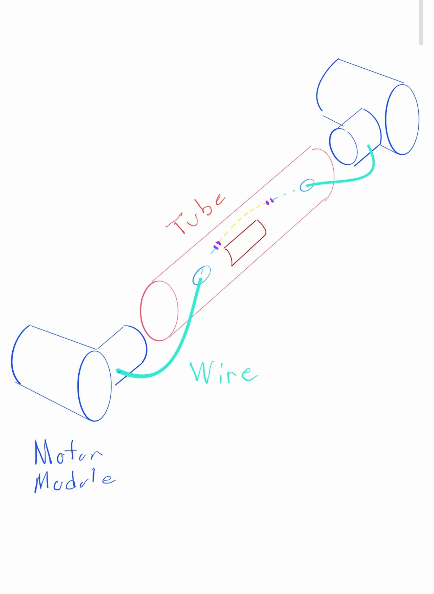
Those are drone-class outrunners pressed into service as joint actuators, tied to the harmonic input by a coupler lathed in-house. Every module carries its own ODrive controller and a custom fuse board inside an FDM-printed ABS enclosure run on a Bambu P1S, so replacing or resizing a motor is a print, not a redesign of anything structural.
The harmonic drive housings and the structural housings around them were contract-manufactured in 6061 aluminum. The harmonic drives themselves were sourced second-hand and integrated into fully custom joint modules.
Links, and the sockets left empty
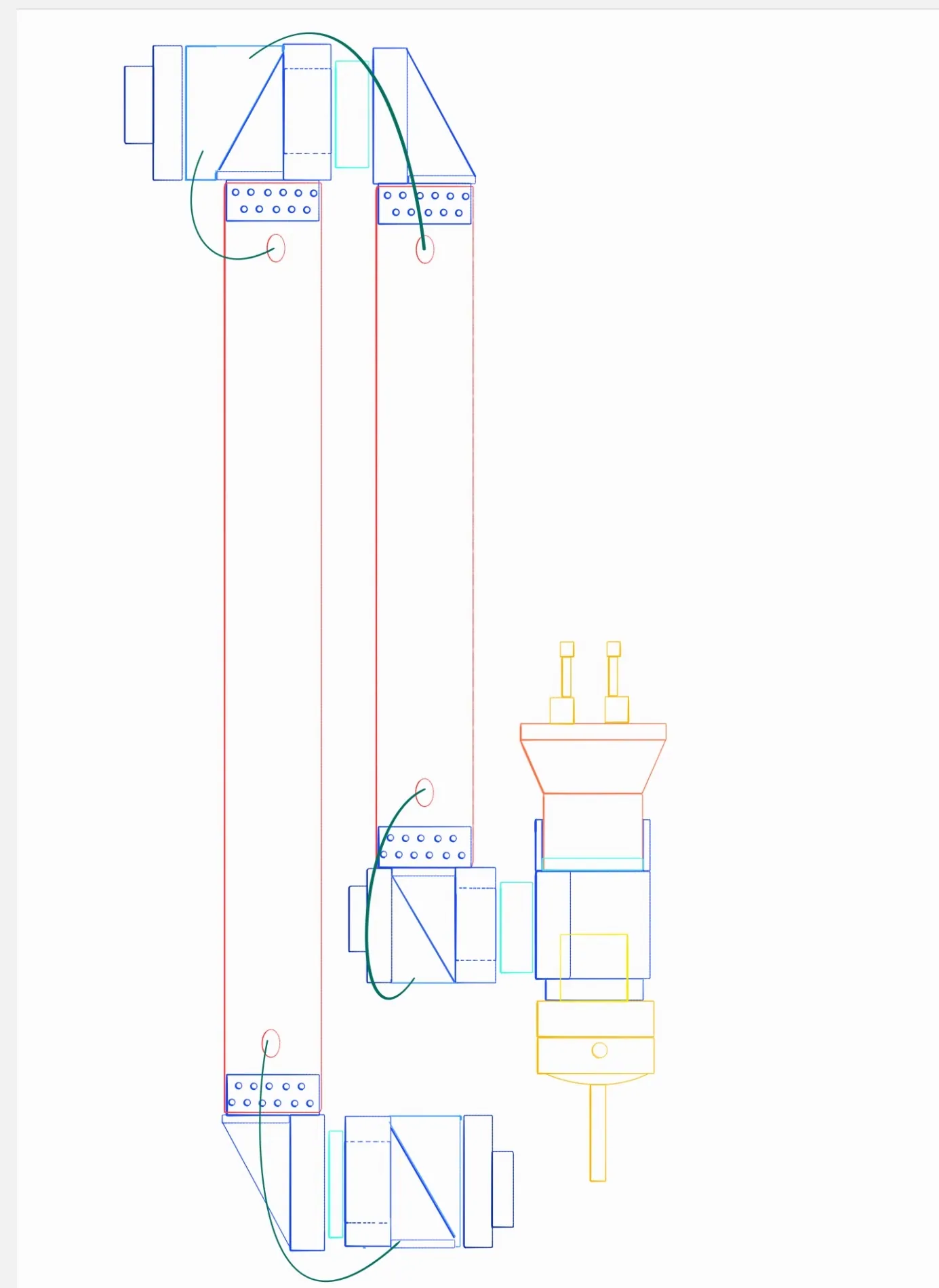
The 6061 tube links come from Industrial Metal Supply with their radial mounting holes cut on a 4-axis laser cutter, which is what makes them drop-in rather than fitted. Because the tube is removable from the modules, link length and link material are both configurable; the planned move to carbon fibre redesigns no joint at all.
The link diagram carries two empty sockets on purpose. An axis can be added where one is currently blanked off.
![Links: 2 in OD 1/8 in and 1/16 in tube, motor modules [1][2][3], empty sockets [1][2]](/img/arm-3-0/16.webp) 24
24Rotating base
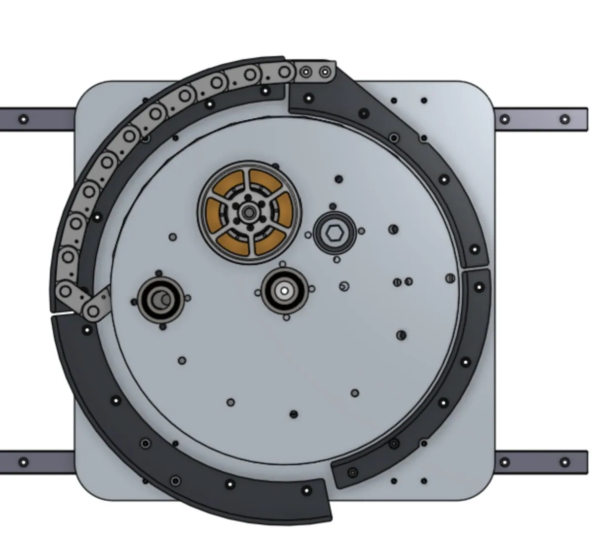
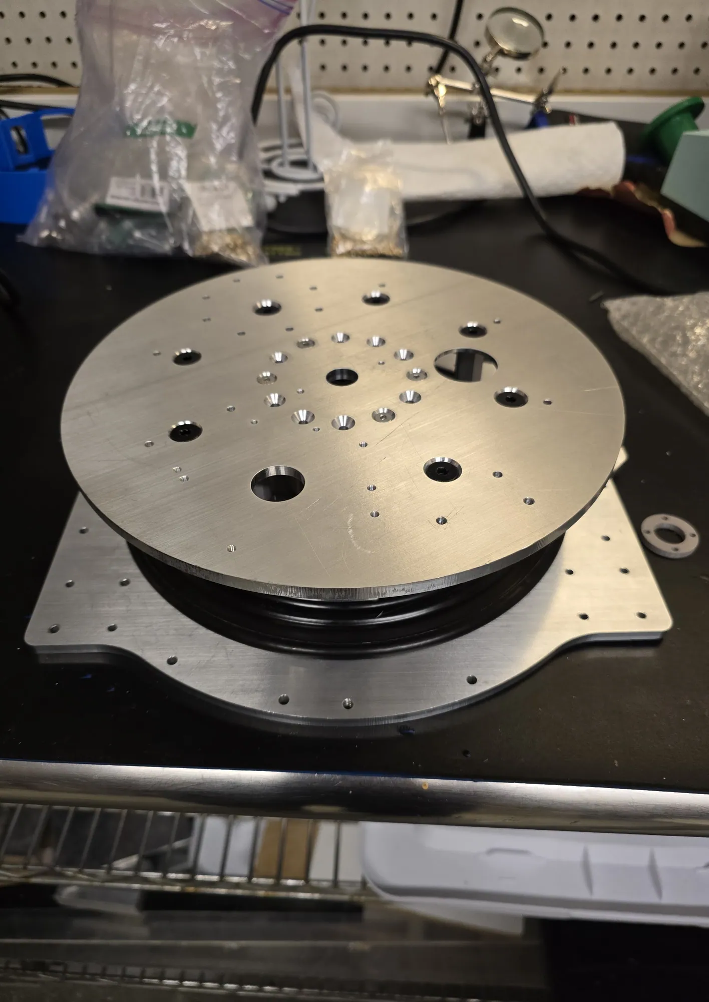
A $35 McMaster-Carr turntable bearing repurposed as a preloaded precision base bearing, clamped by a 0.5 in dead centre shaft between 0.25 in waterjet 5052 aluminum plates. A CM-AKE60 with an integrated ODrive encoder drives it through a 6.75:1 compound reduction (a belt first stage into a planetary second) for 34 Nm under closed-loop position control.
The planetary stage turns around a fixed sun gear with a driven planet carrier; the sun gear is custom waterjet 5052 and the structural parts around it are ABS. A custom E-Chain routes power and signal through the rotation axis for continuous 360° travel, which matters when the arm indexes around a servicing panel instead of unwinding between attempts. I developed the E-Chain and handed it to another team member to finish.
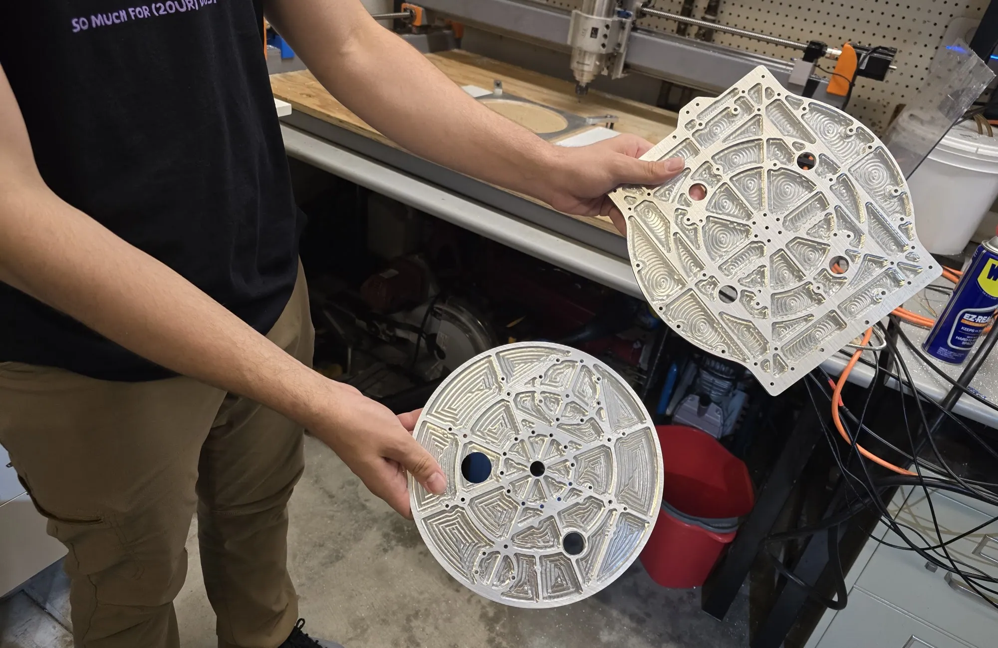
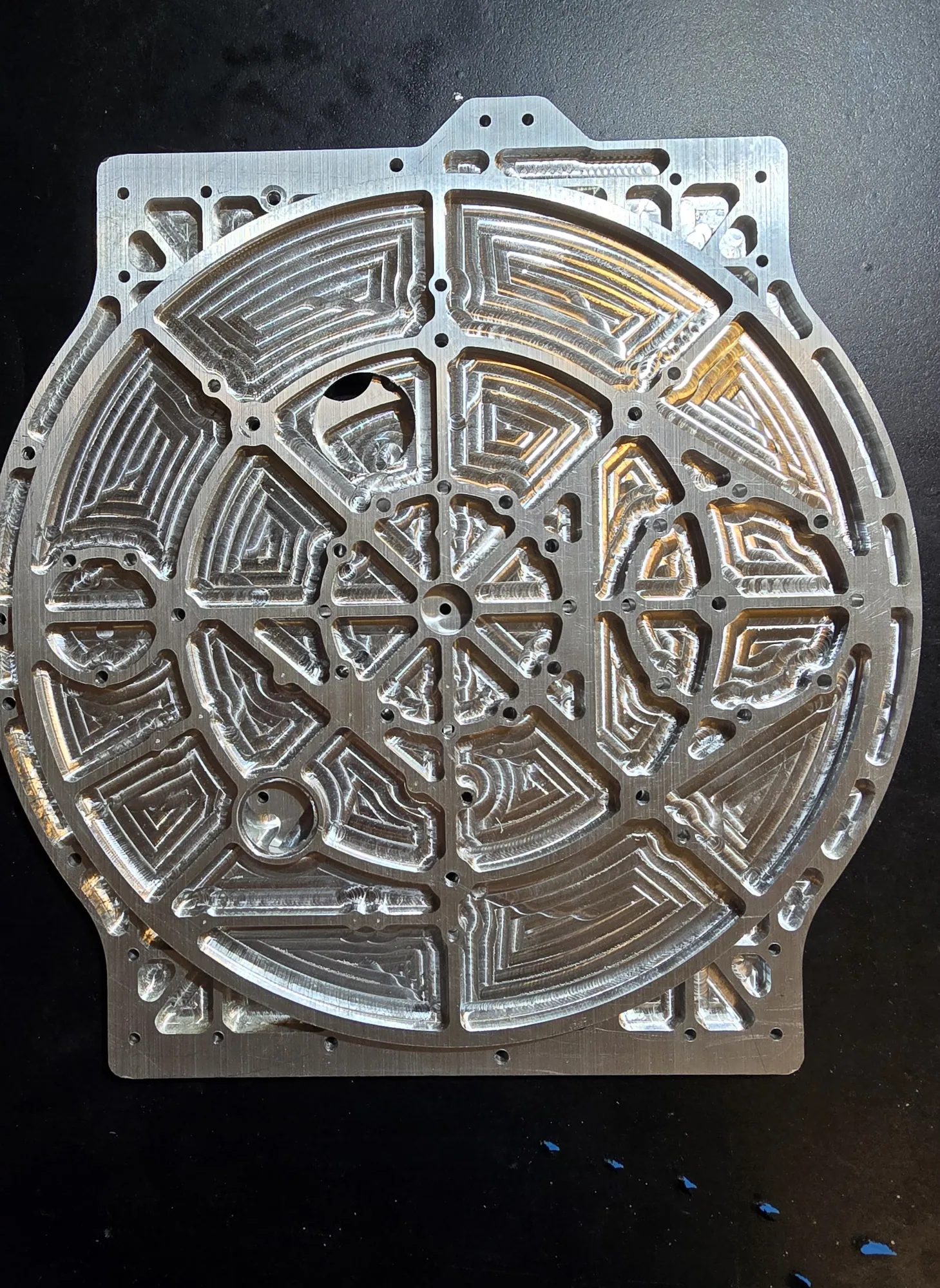
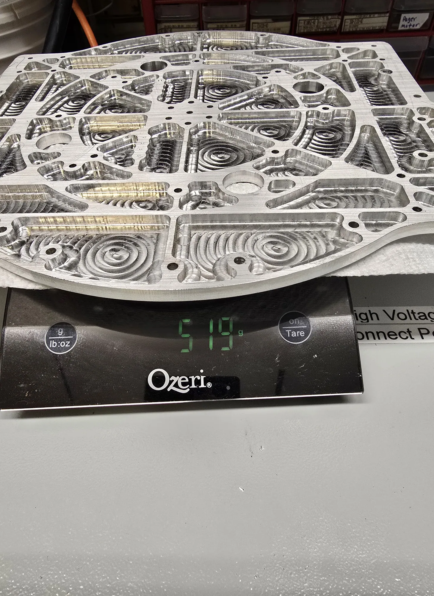
The plates are pocketed down to a lattice, and the finished plate came off the mill at 519 g. The base interfaces directly with the shoulder motor module and the arm structure above it.
Linear slide
The second base axis lifts the entire arm rather than asking the shoulder to reach for height. A motor drives a chain against a rope-tensioned second stage, with the carriage riding bearing blocks on the extrusion.
Two stages give the working envelope the vertical range to reach both a ground sample and a panel at chest height from one rover position.
 39
39Perception mast
Developed alongside the arm. It gives automation and simulation a stable camera reference frame. The arm and the perception stack have to agree on where things are, and that agreement is only as good as the mount's rigidity.
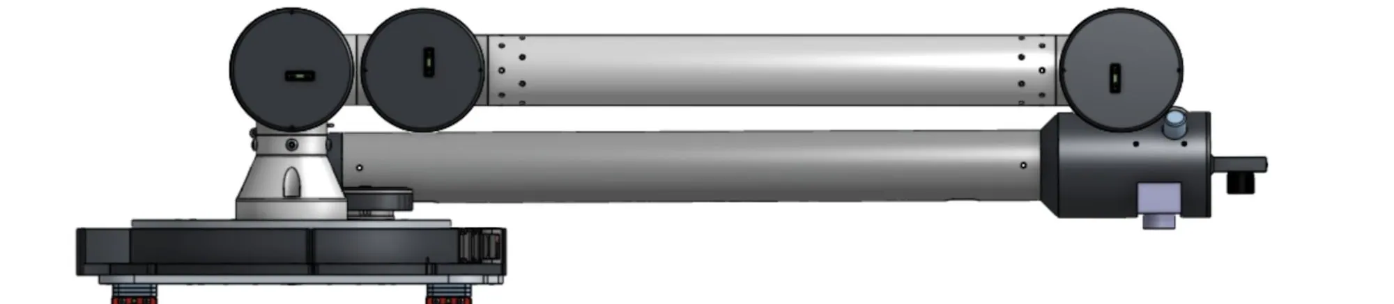
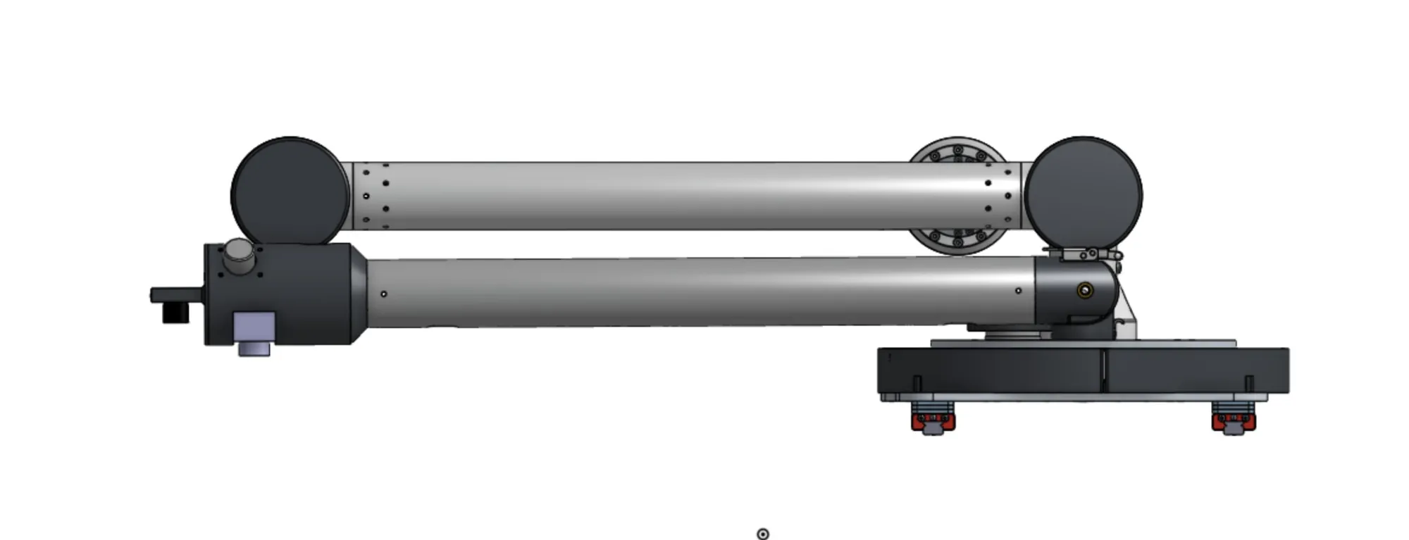
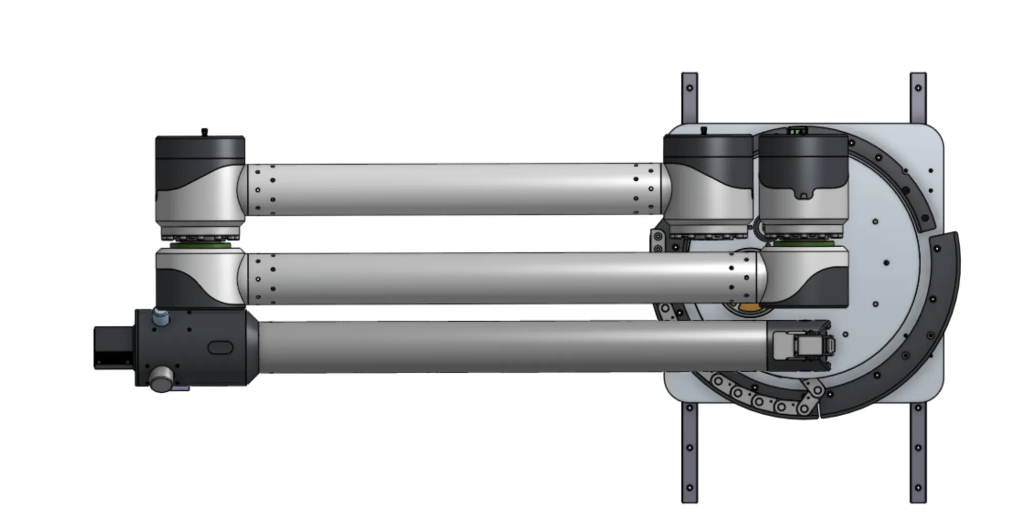
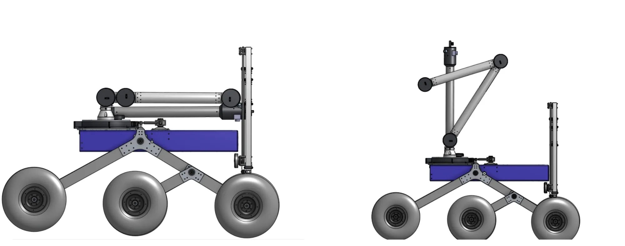
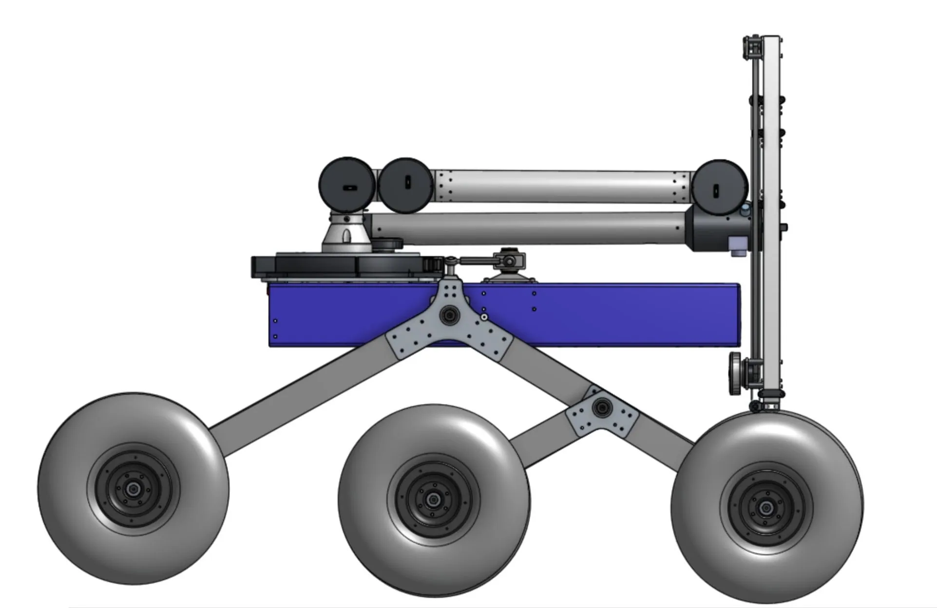
The arm fully collapses horizontal for transport, mast included.
 03
03Sized for 5 kg at 2.5×
Verification started in a spreadsheet, not in FEA. I built a mass breakdown of every major component, treated each as a point mass at a radius from the base, and summed torque contributions (τ = w·r) along the chain, including the 5 kg payload, evaluated fully extended, the worst case for both motor demand and structural load. That model is what sets the 2.5 factor of safety the design is built on; the value of 2 in the older PDF is outdated.
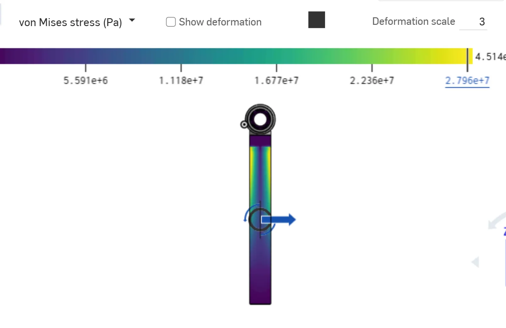
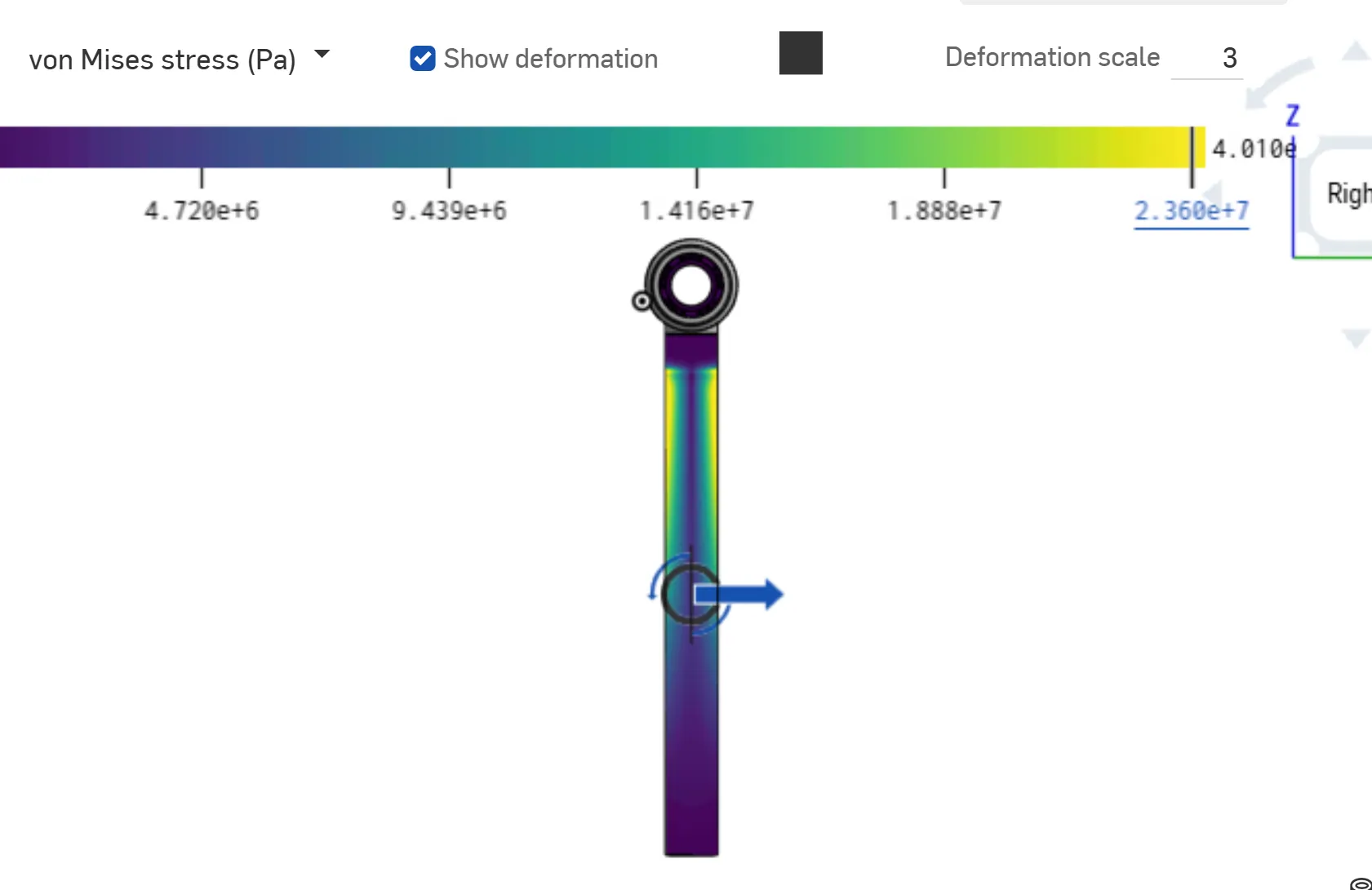
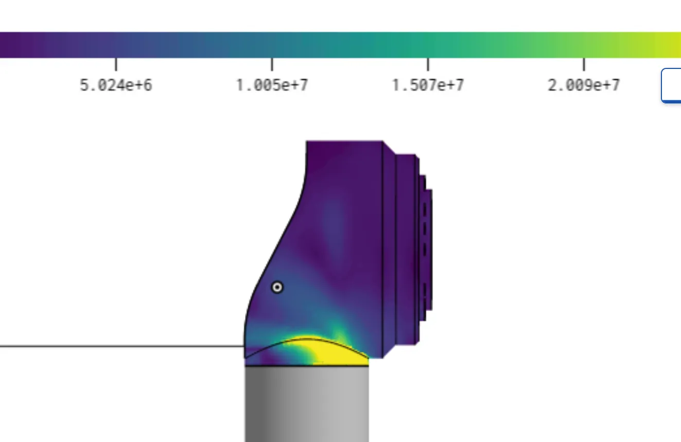
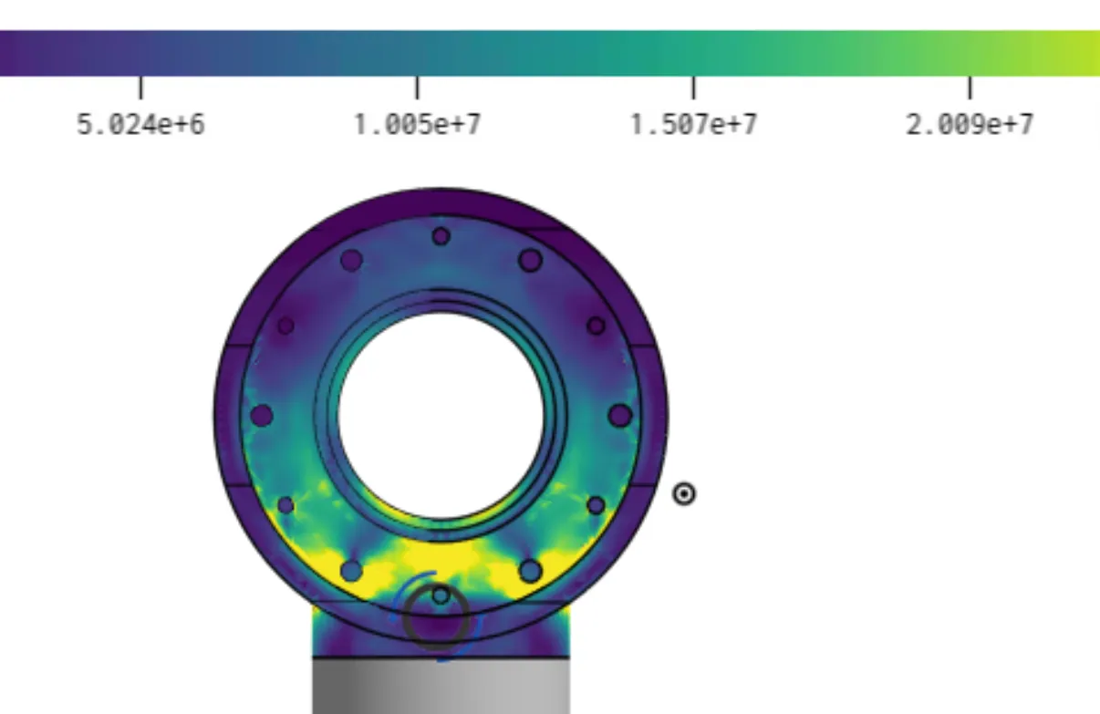
The same model produced Z-direction shear and bending moments, symmetric loading cases included, and those combined conditions became the inputs to the tube and module FEA.
FEA showed minimal deflection and a wide margin, and it changed the design once: an early iteration deflected about 1 mm at the bottom tube, which we judged too much for future accuracy and robustness, so its wall went from 1/16 in to 1/8 in. That is the step you see between the lower and upper link.
Gallery
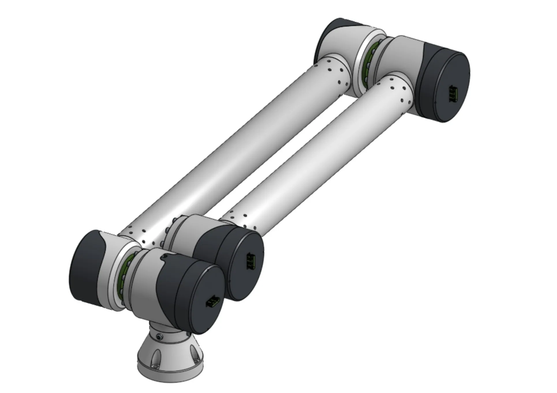
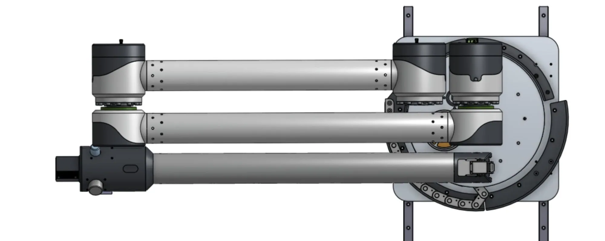
Arm assembly
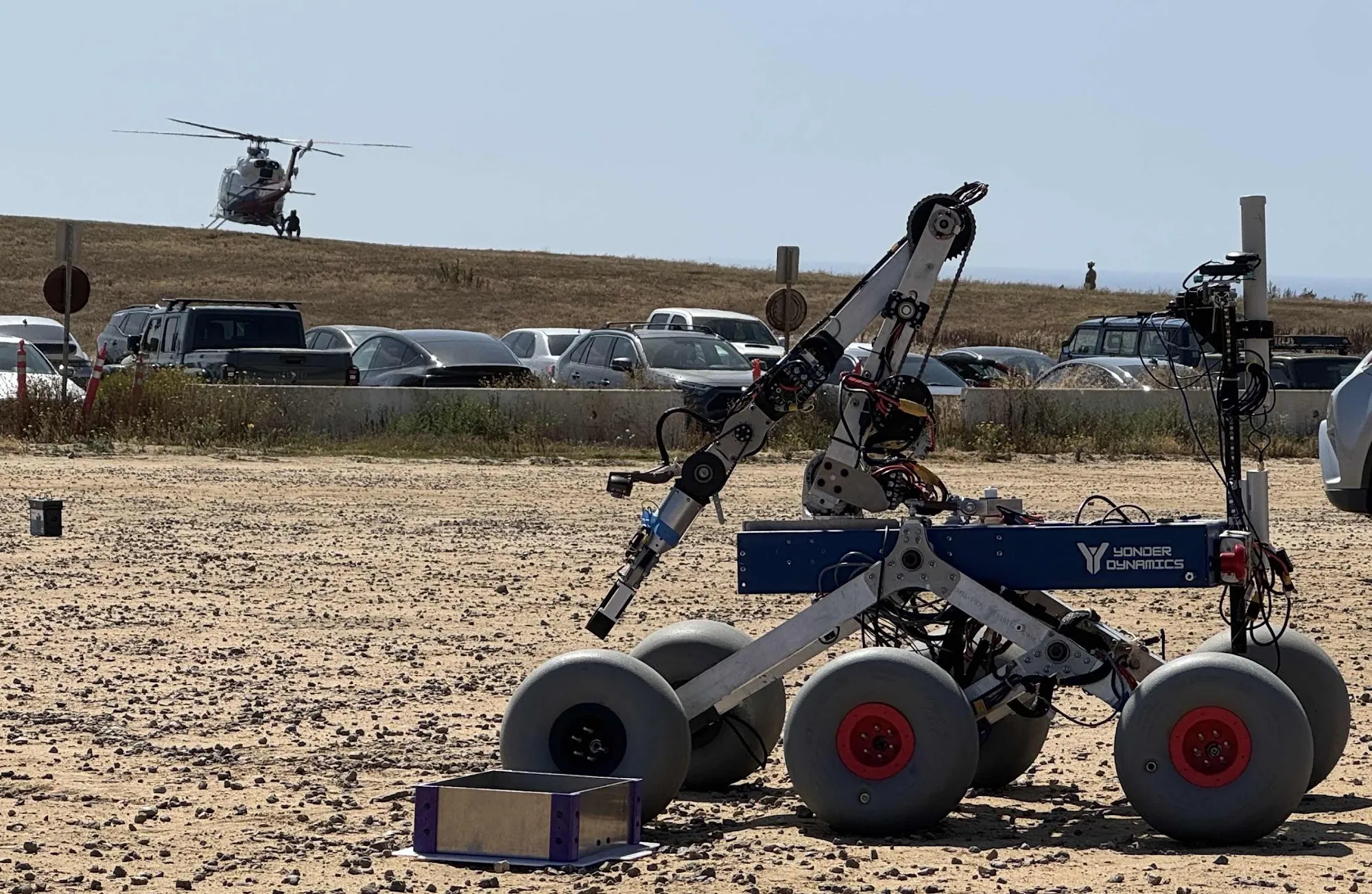
Deployed, extended, and folded flat for transport.
On the rover
Arm and mast integrated on the chassis, and in the field.
Motor module
The unit repeated at all three joint scales.
Rotating base
From printed plate to machined lattice to assembled turntable.
Load model and FEA
The bracket and bearing faces the modules clamp to.
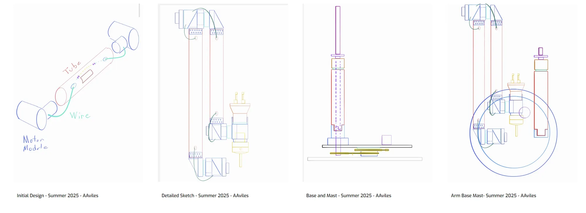
Concept and requirements
Where the architecture came from, Summer 2025.
Yonder Robotics