
Yonder Robotics · 2025–2026
Motor Module
The standardized joint for current and future rover arms. A one-piece machined harmonic drive housing at 100:1, a printed motor housing that swaps with the motor, and the ODrive, magnetic encoder, and fuse board all packaged inside the module, so a joint is a part you fit, not an assembly you design.
Why a module at all
Brainstorming started from what ARM 2.0 got wrong. Its joints were structurally integrated into the tube stock, so changing the link length between shoulder and elbow meant redesigning the arm. The REV gearboxes brought backlash. Motors, controllers, and wiring were all separate items, which is more mass, more complexity, and more places to fail.
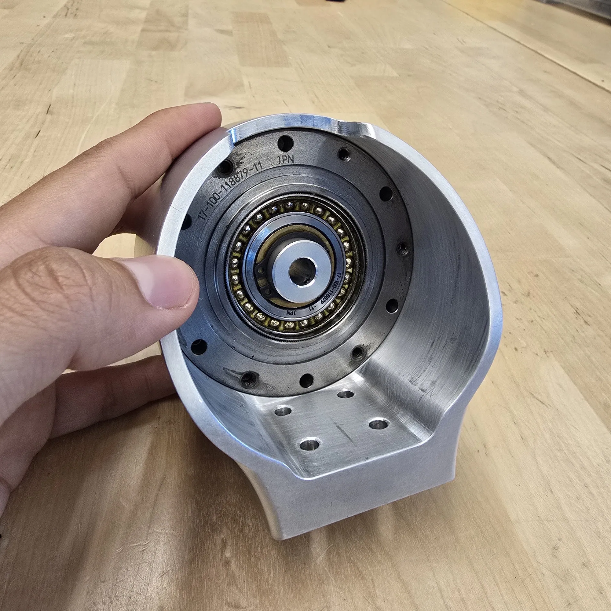
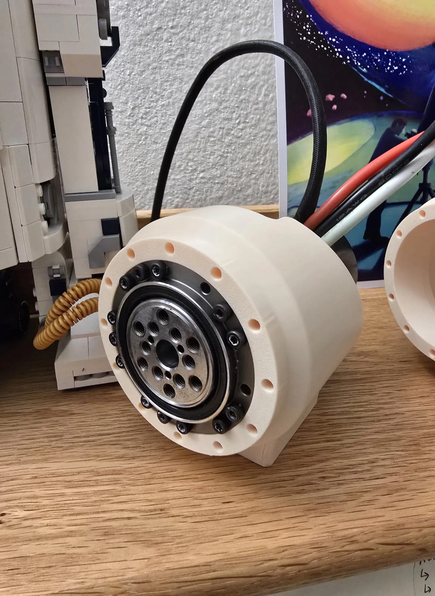
Integrated motor modules are the standard answer (motor, reducer, encoder, and controller in one unit), so the requirements wrote themselves: modular, compact, lightweight, high torque, low backlash, adaptable. Harmonic drives were chosen for torque density and near-zero backlash, and the modules were designed around Harmonic Drive 17-100-118879-11 reducers sourced secondhand.
What is inside one
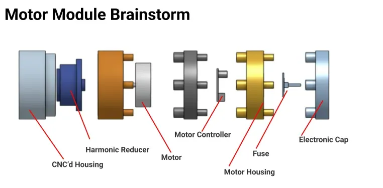
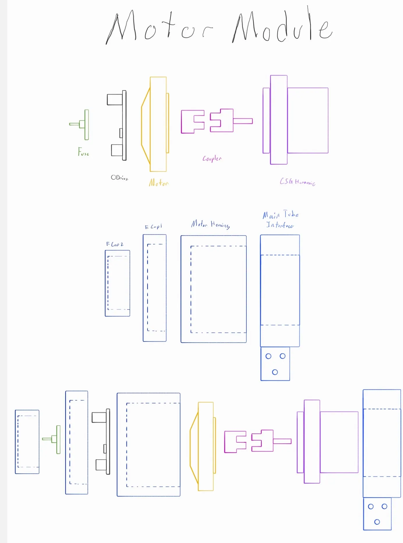
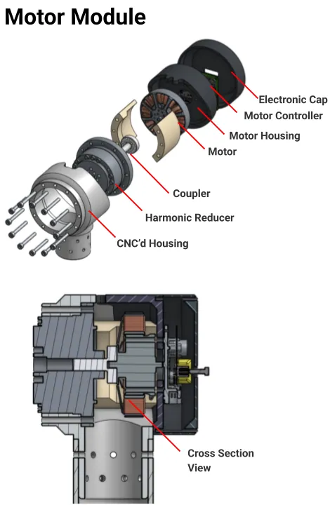
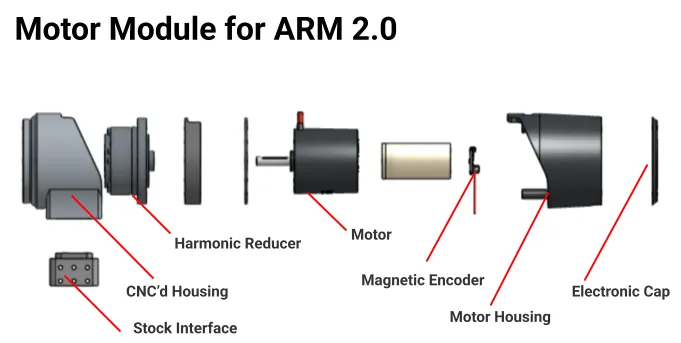
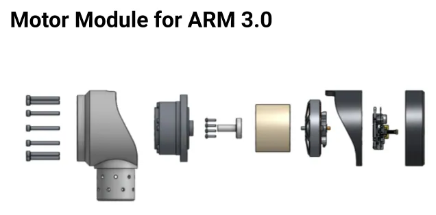
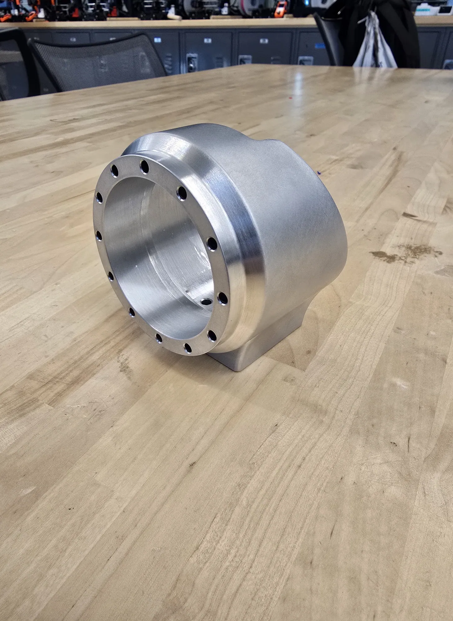
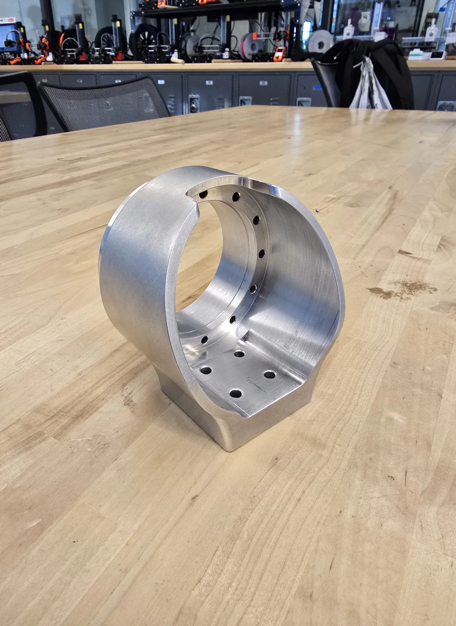
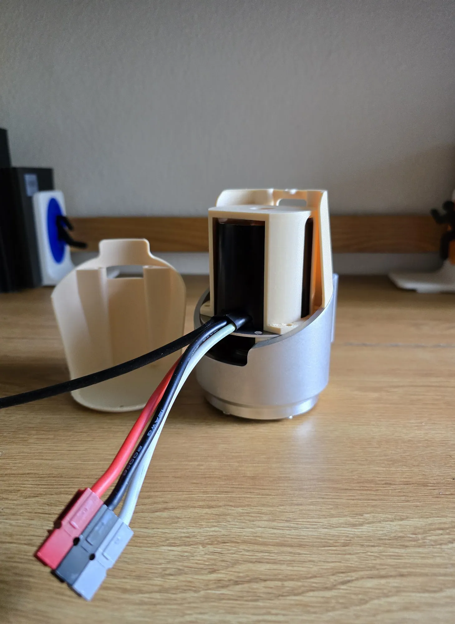
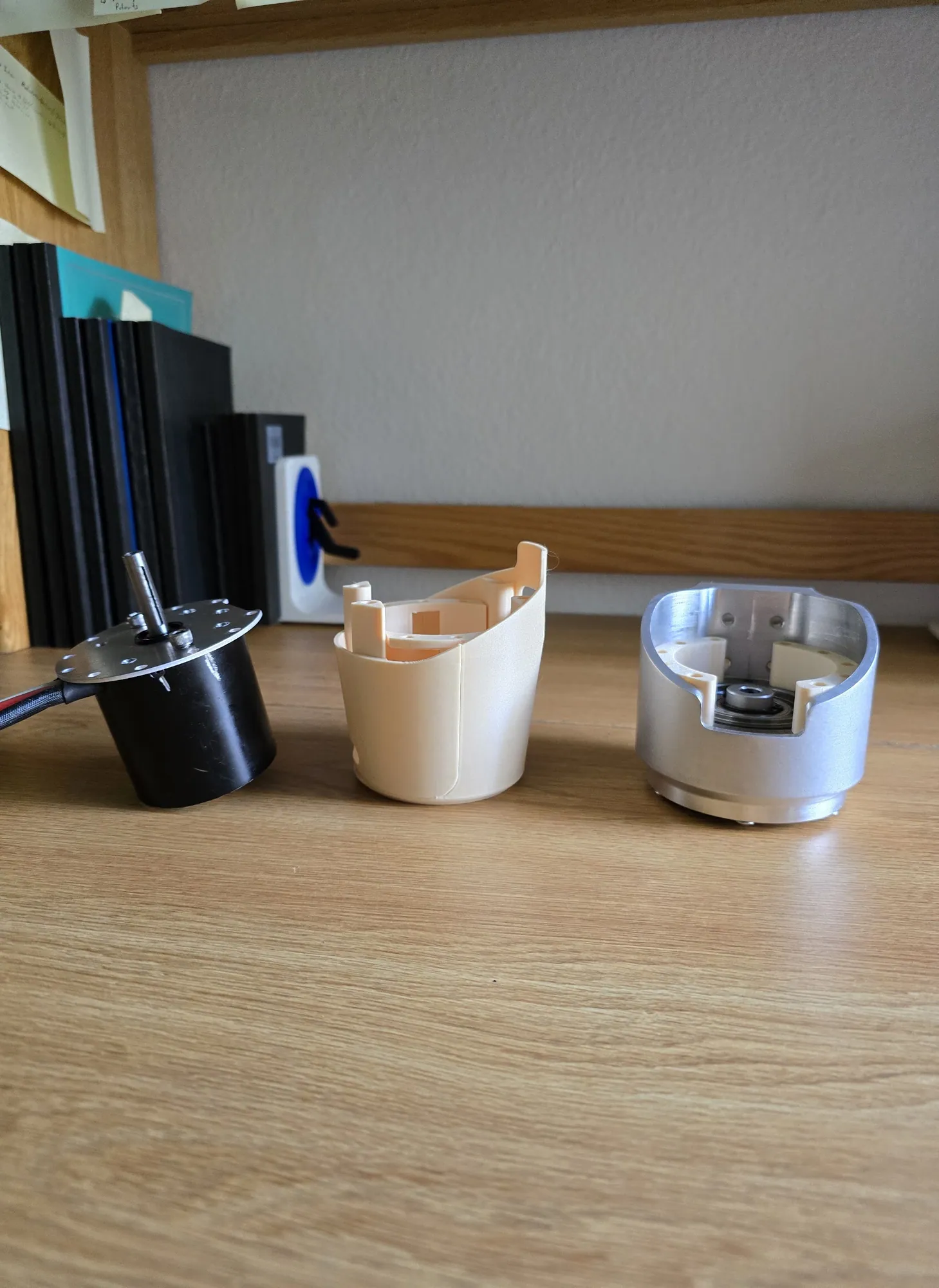
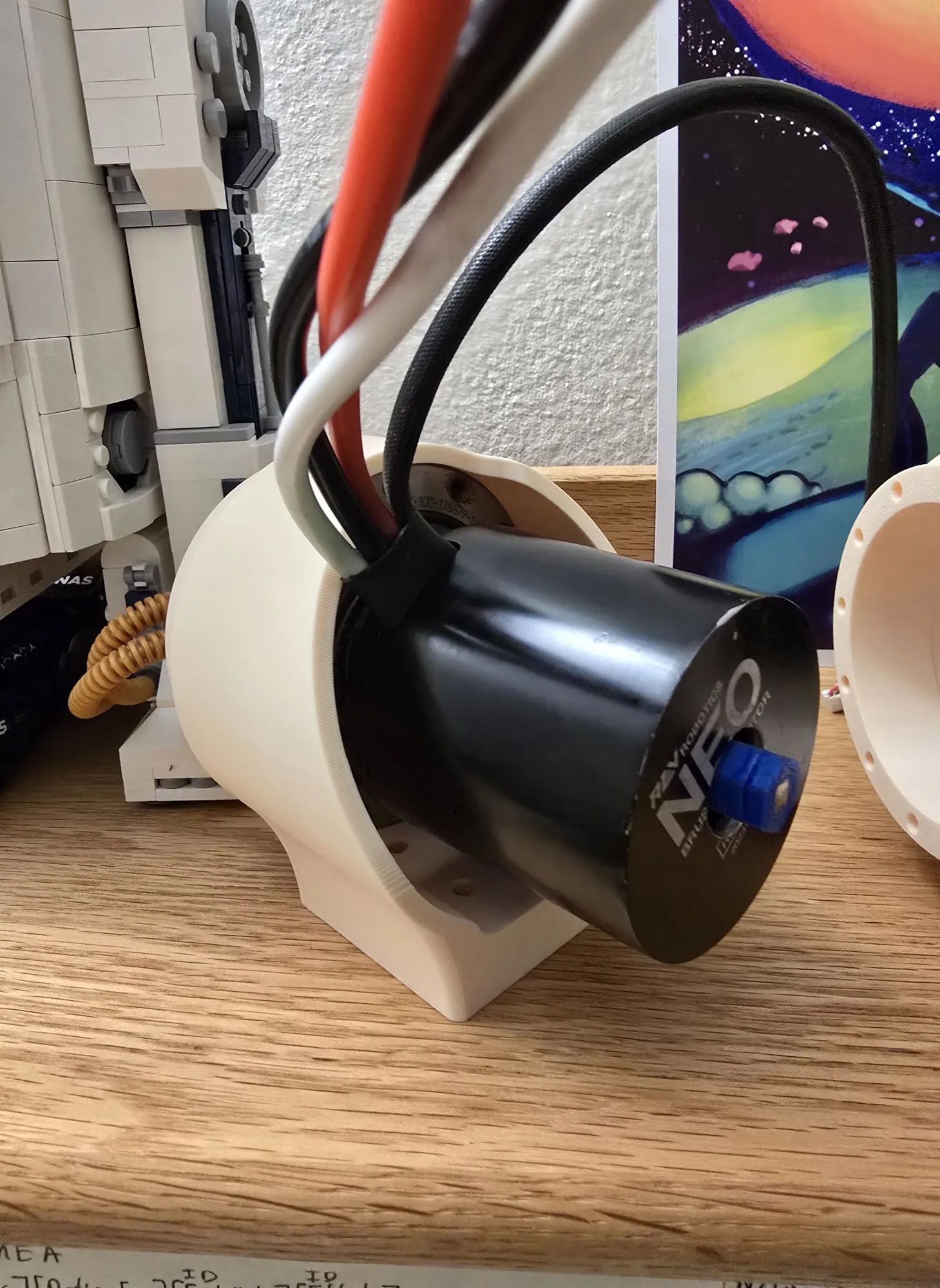
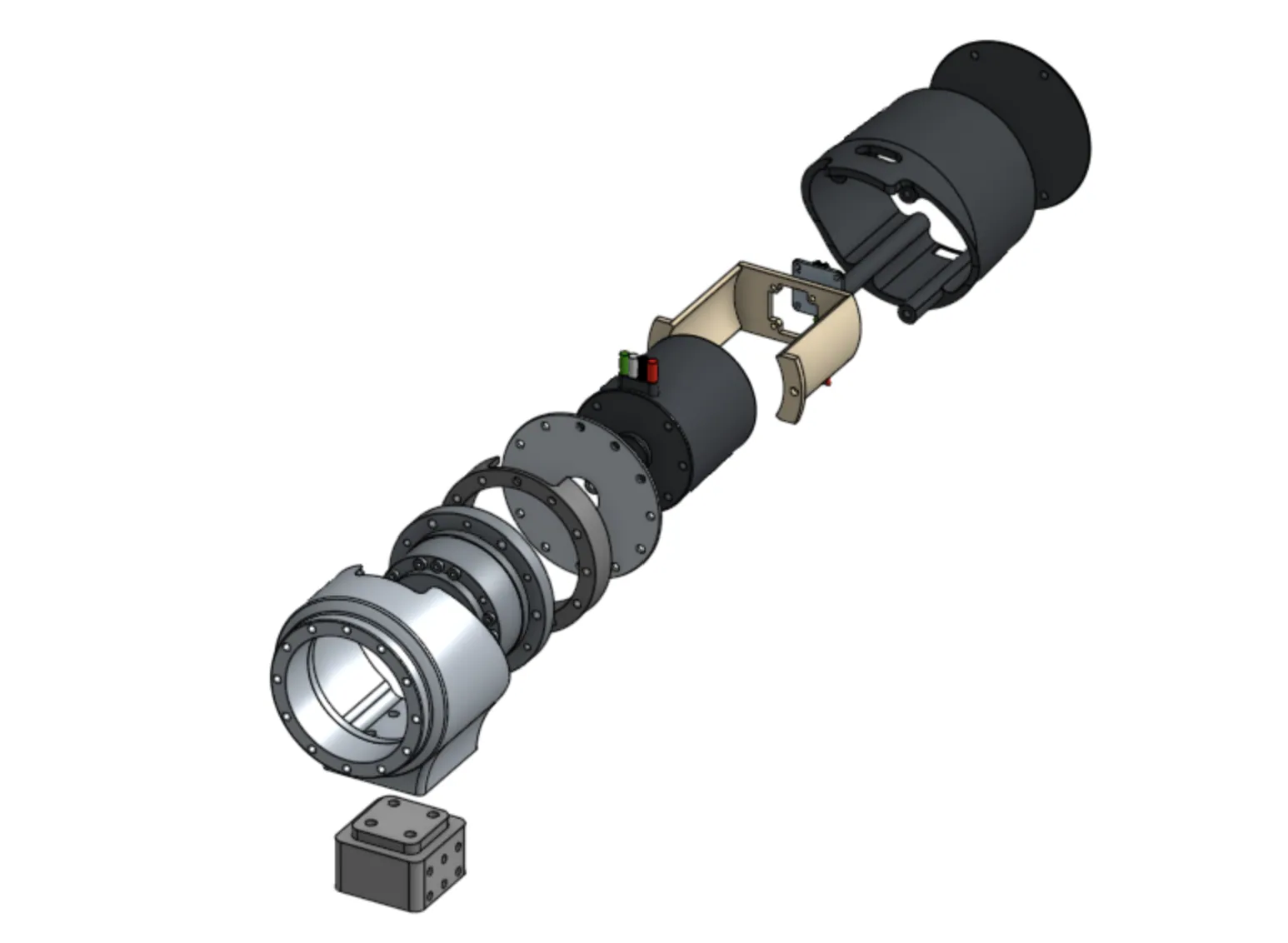
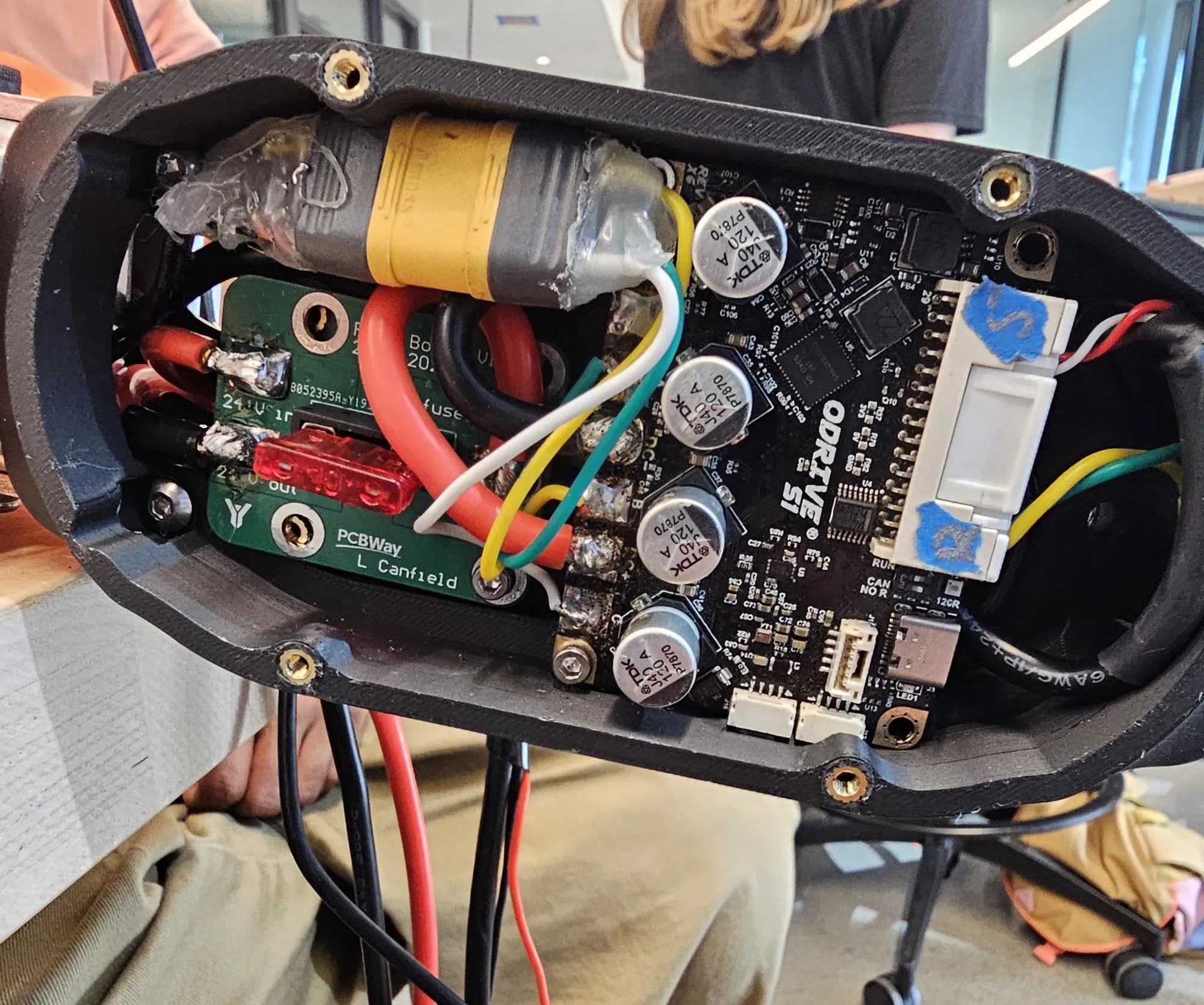
From the output face inward: a one-piece CNC aluminum housing, the harmonic reducer, a lathed coupler, the motor, a printed motor housing around it, the ODrive controller, a custom fuse board, and an electronic cap that closes the back.
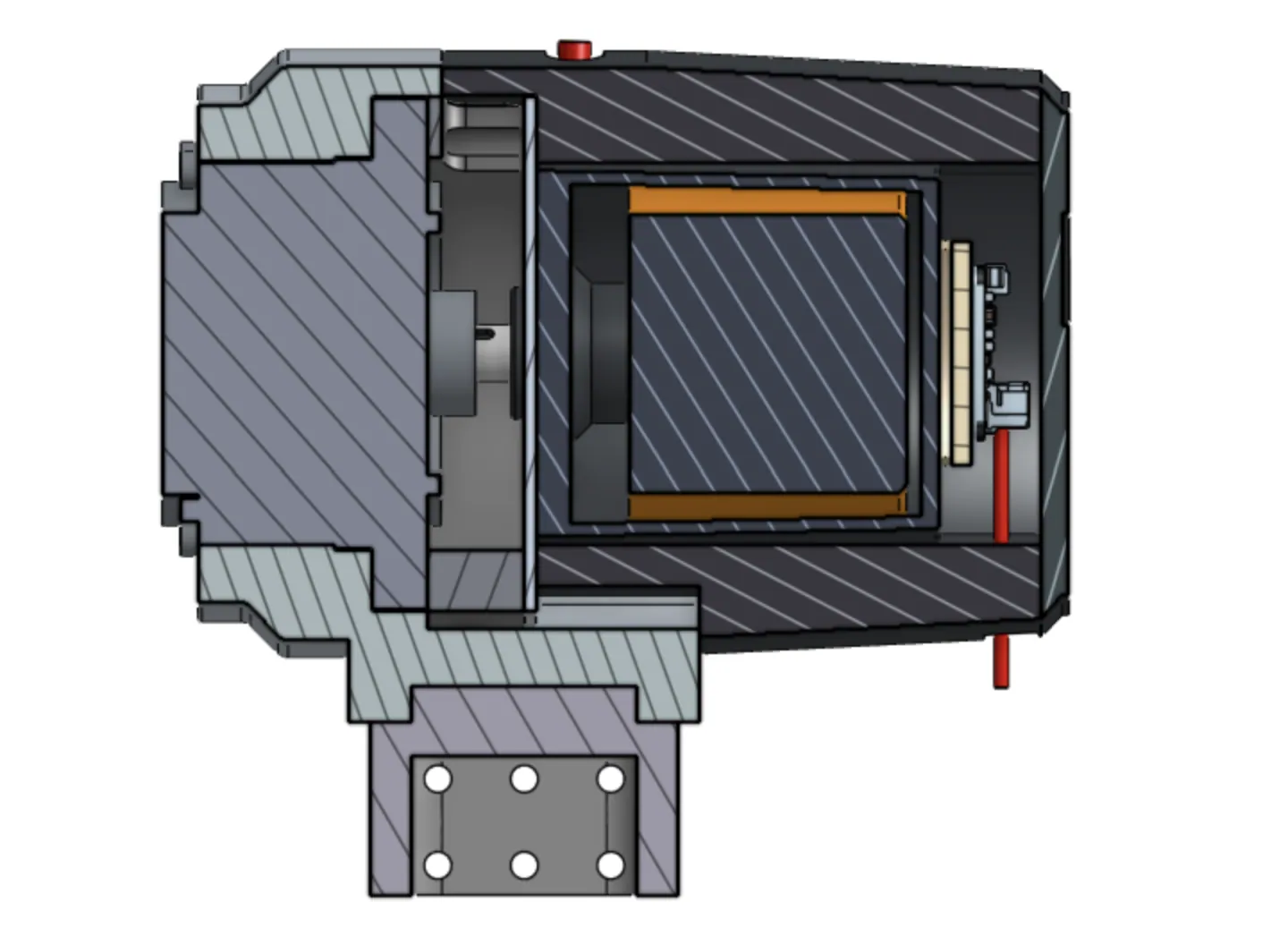
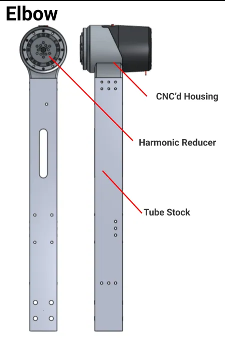
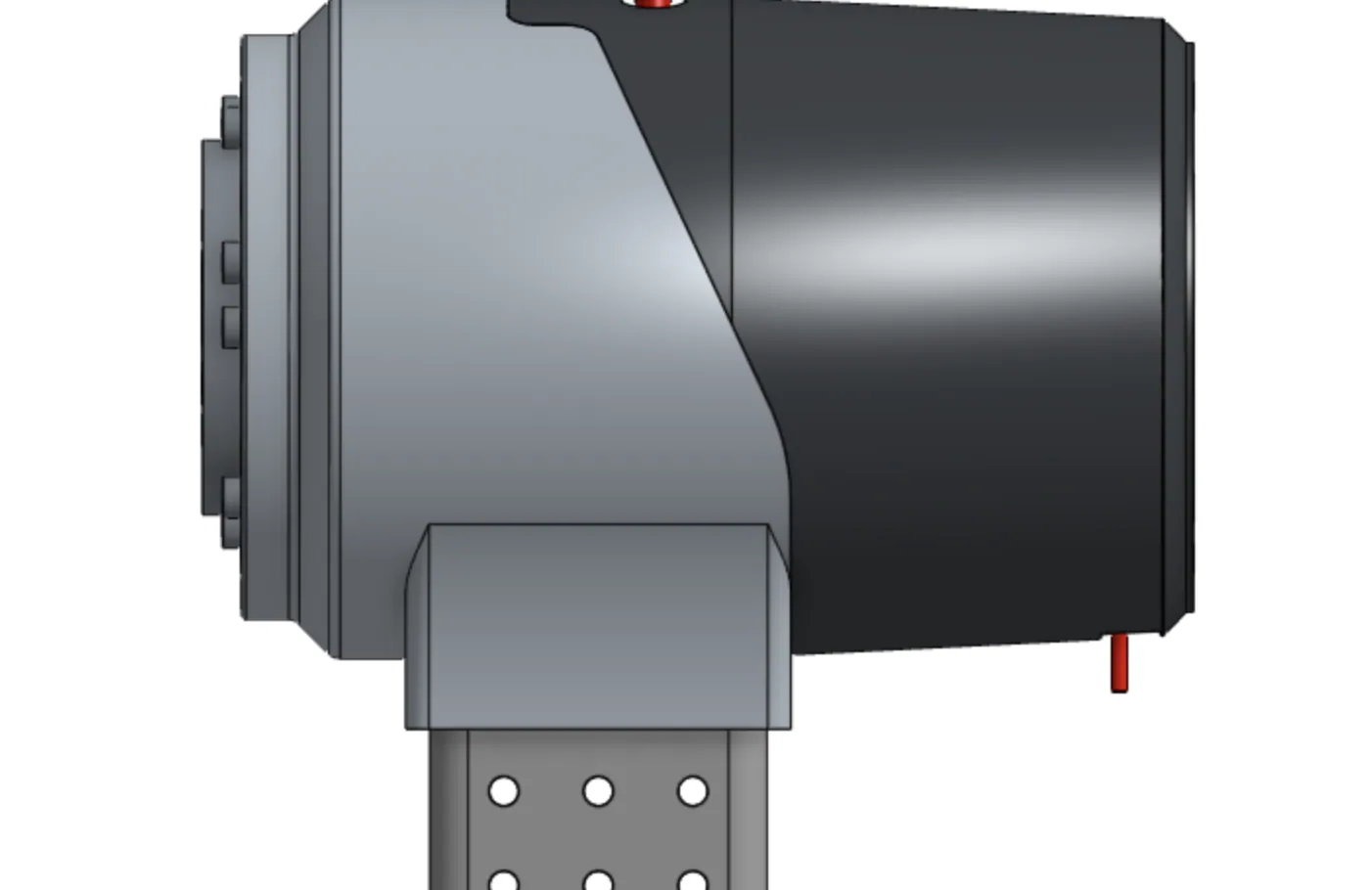
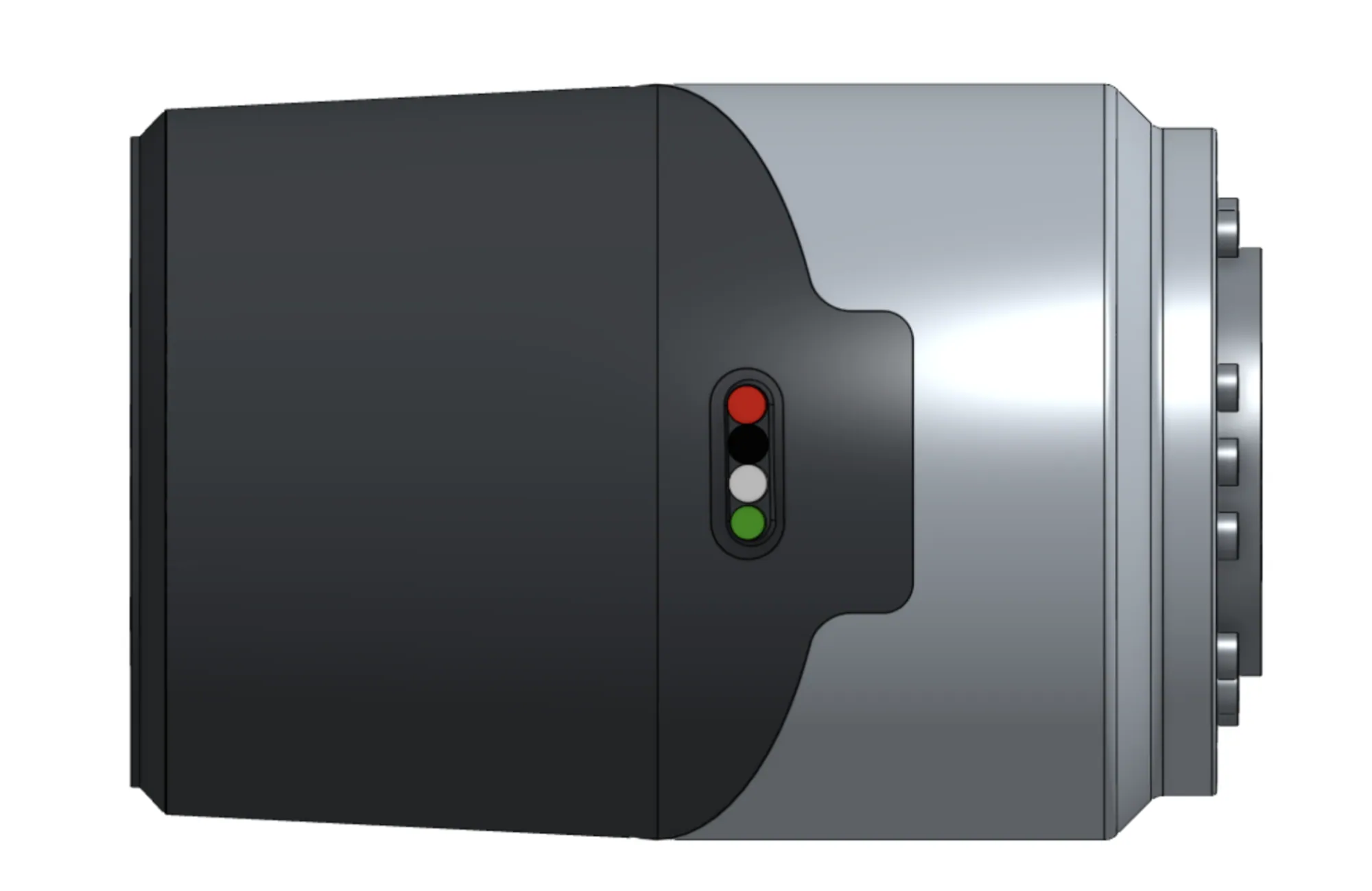
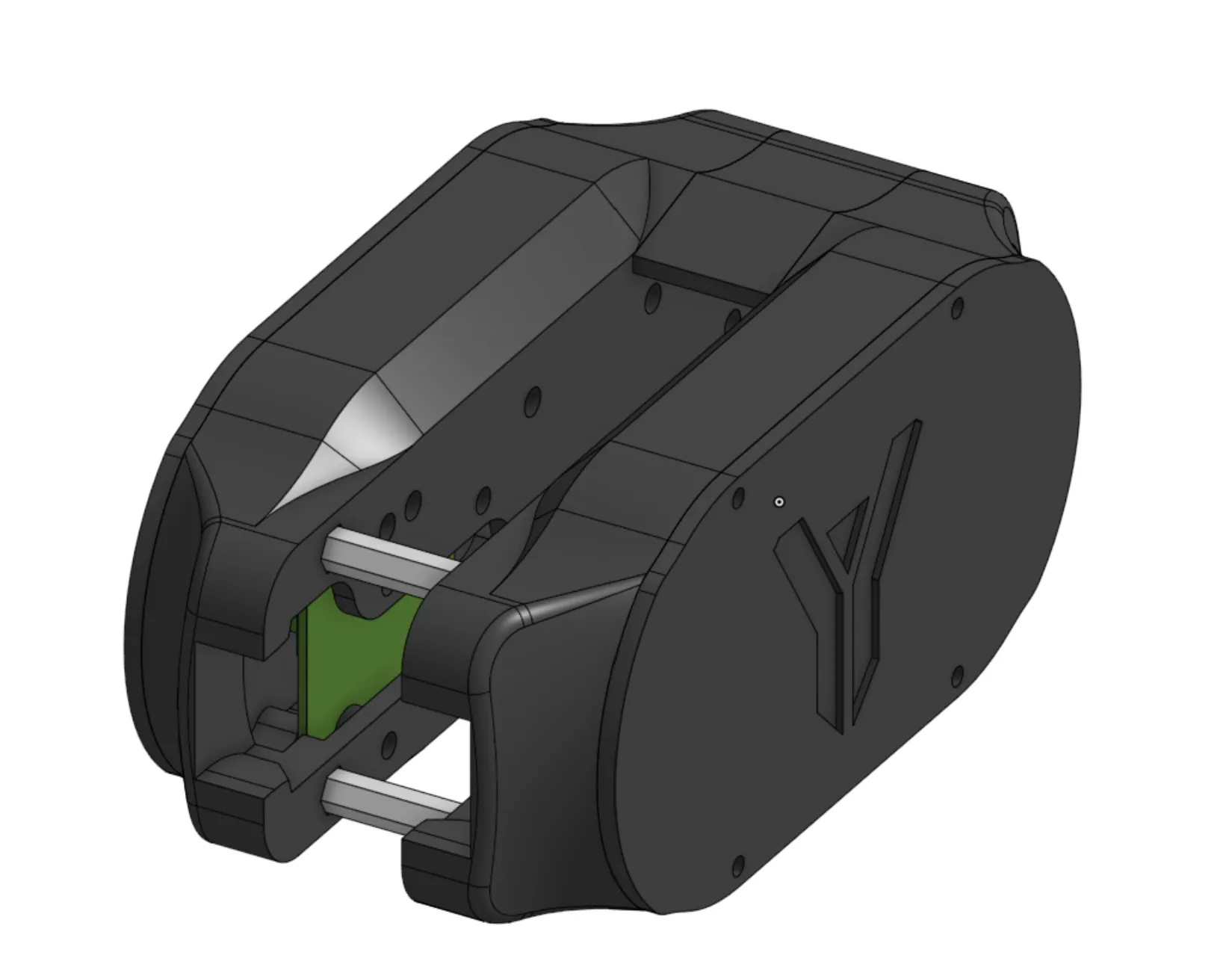
Nothing hangs off the joint. The structural interface, the reduction, the actuation, and the electronics all live inside one envelope, which is what lets the tube links between joints become plain stock.
Two variants, one architecture
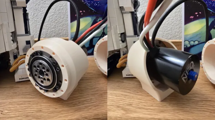
The ARM 2.0 module is a retrofit. It carries a NEO 1.1 with a magnetic encoder and ends in a stock interface, so it could be dropped into an arm that was never designed around modules.
The ARM 3.0 module is the production form: the same harmonic reducer and the same housing concept, with a scaled T-Motor outrunner chosen per joint and the housings contract-manufactured. The motor housing is the only part that changes between the three joint scales.
Validated before it was multiplied
Following a Master Validation Plan, one module was designed and machined to retrofit ARM 2.0's elbow. Its job was to prove the mechanical interfaces, the tolerances, and the manufacturability of the concept while a mistake still cost one part.
It worked, and only then were the ARM 3.0 modules contract-manufactured, a fully modular joint architecture independent of the arm structure around it.
Verification and manufacturing
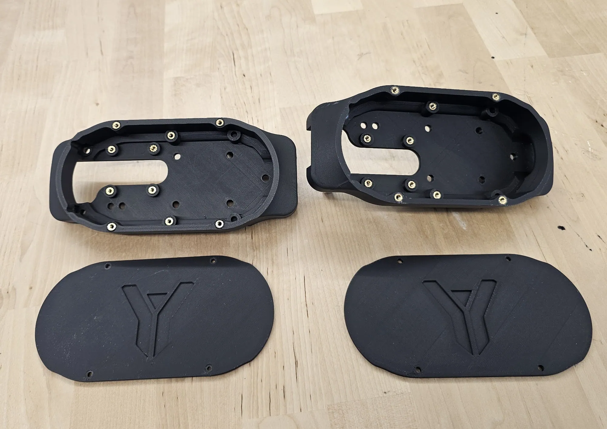
Manufacturing ran prototype to production. Housings were FDM printed on a Bambu Lab machine first, to check fitment, assembly clearances, and general tolerances before any aluminum was cut.
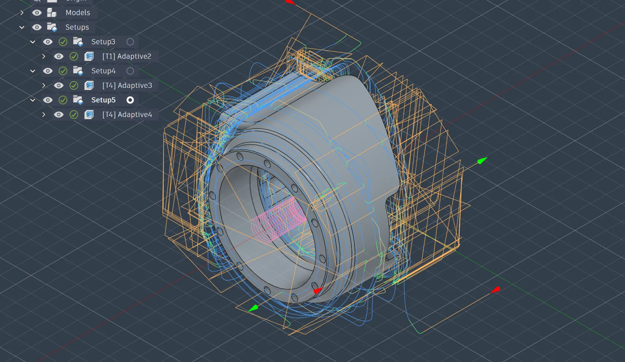
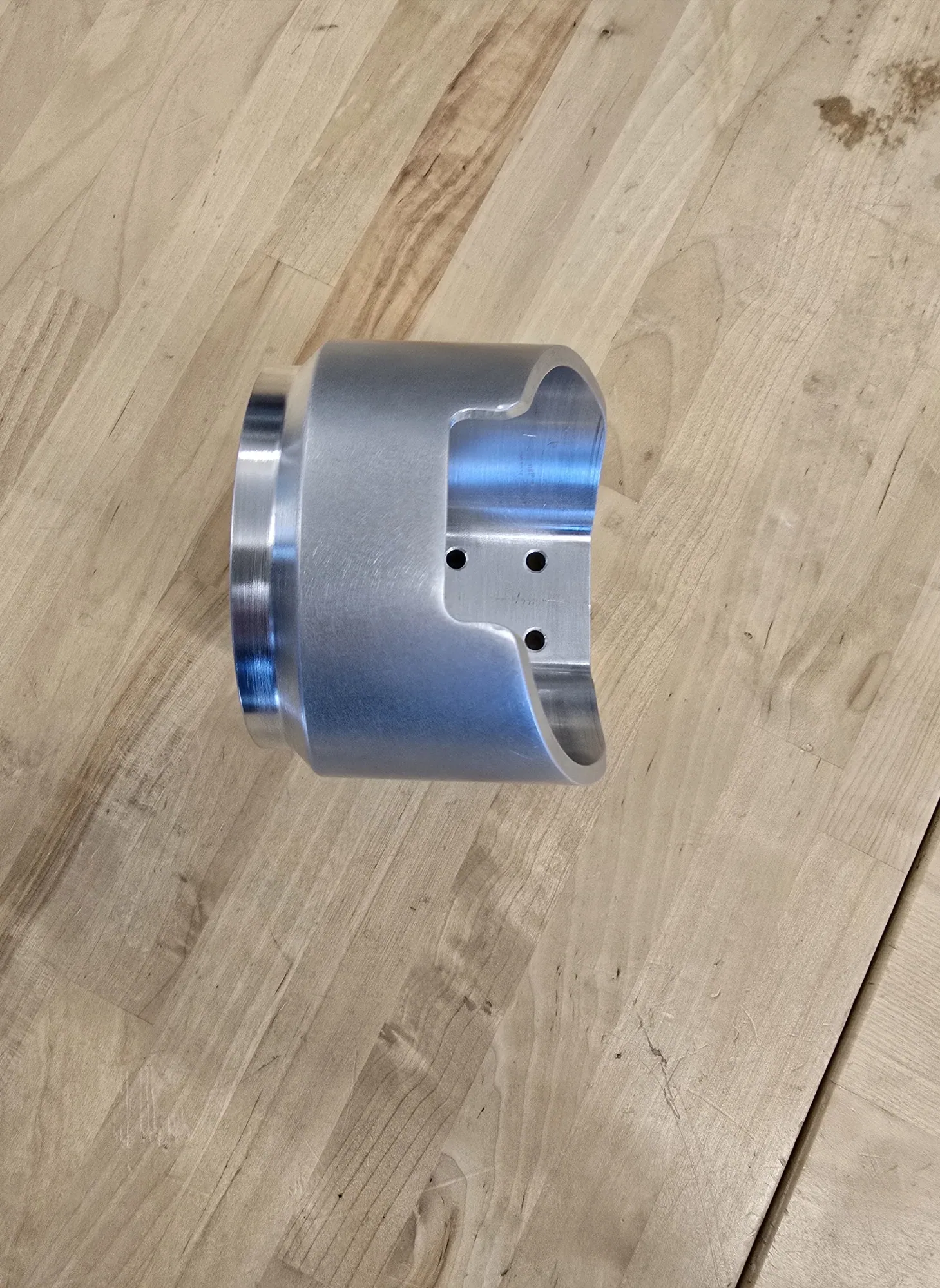
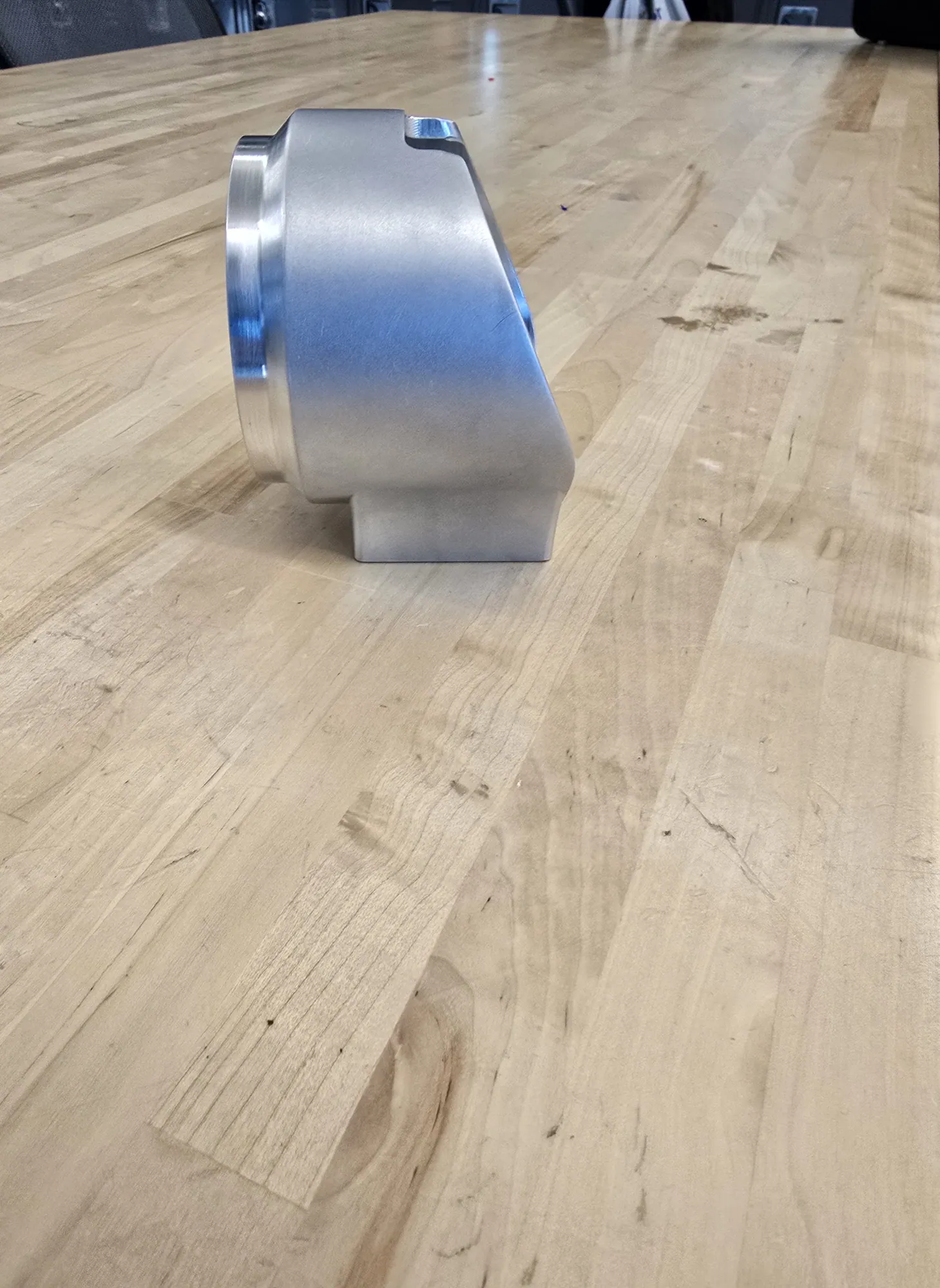
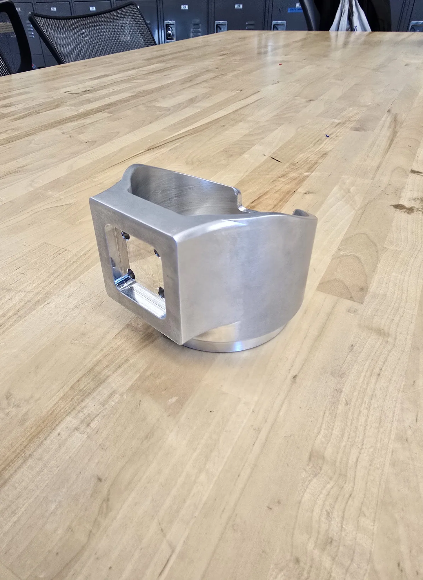
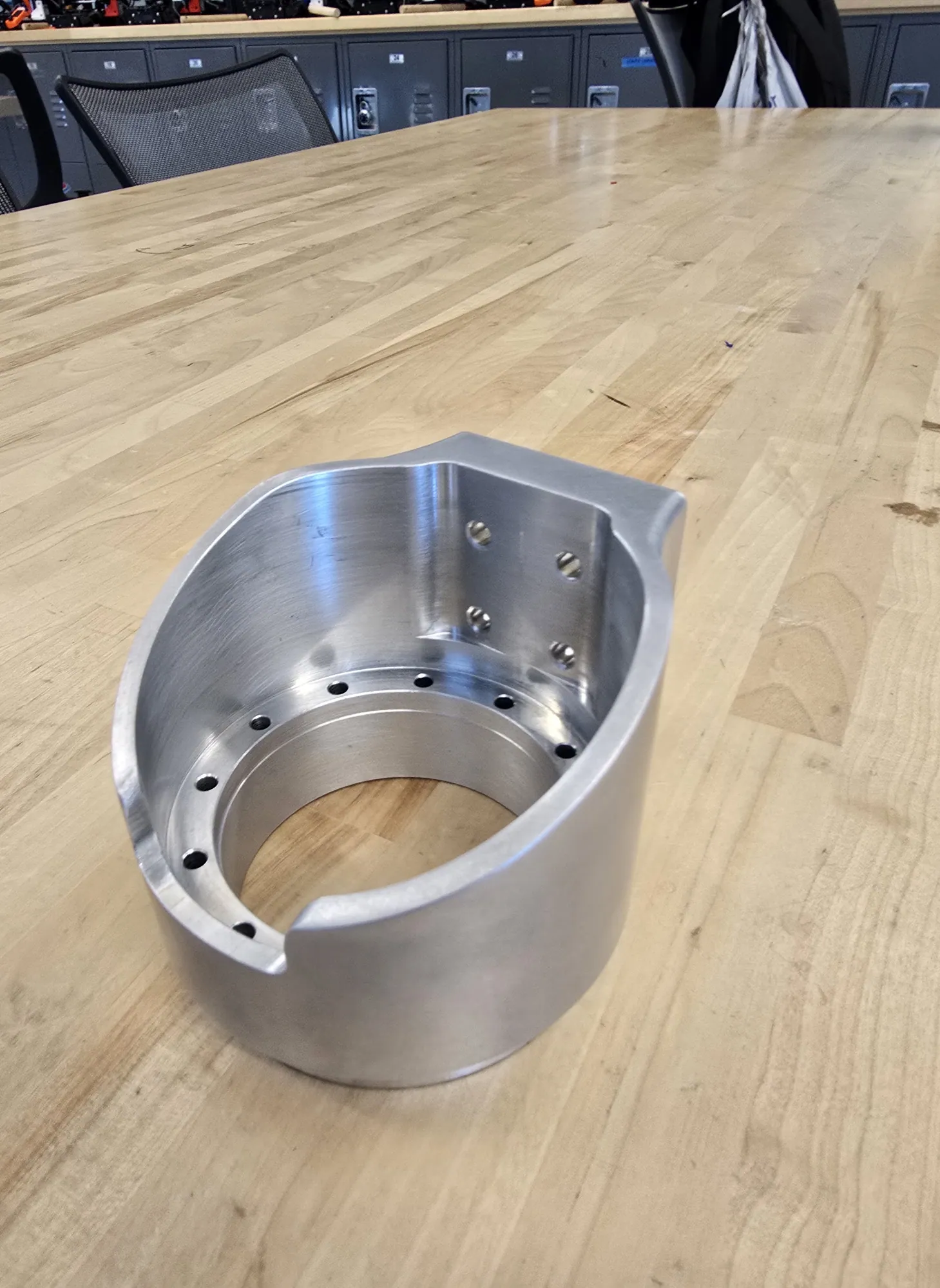
Final parts were CAM programmed in Fusion 360 and machined on a Tormach mill in three setups, which is what holds alignment between the harmonic drive interfaces and the structural mounting features on a one-piece part.
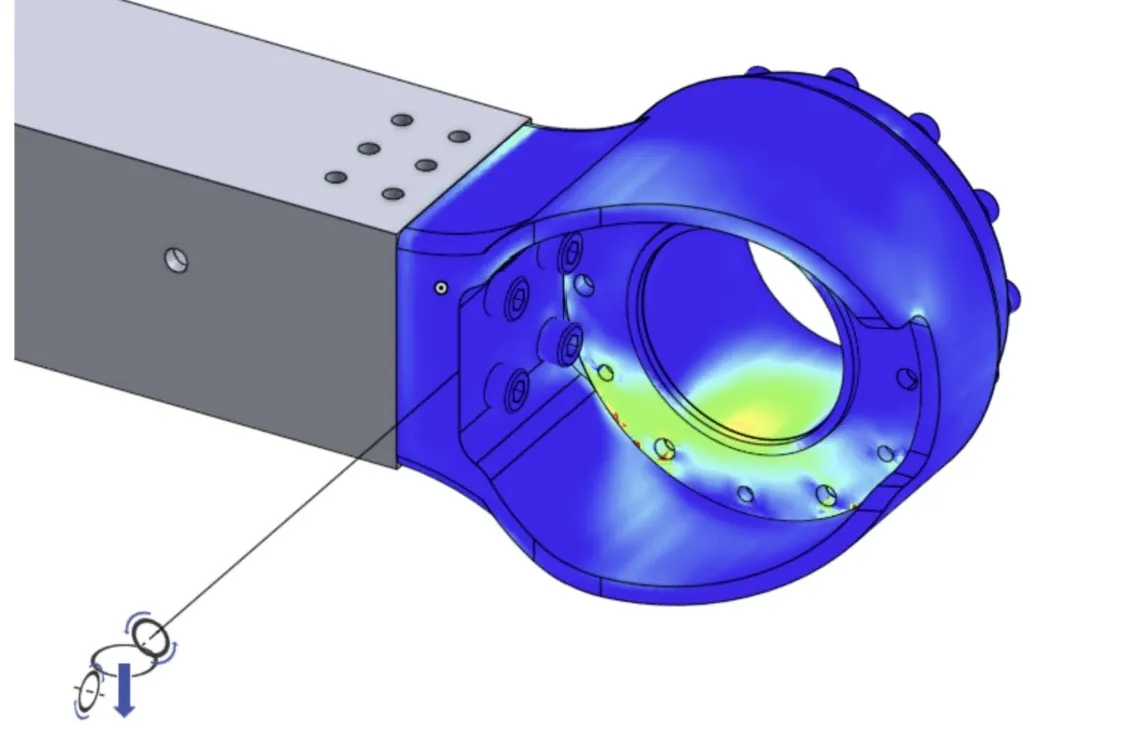
Structural verification used FEA under the worst-case loads taken from the spreadsheet torque and shear model. Early analysis found stress concentrations at internal corners; the fillet radii went up to spread the load. The final results show low stress, minimal deflection, and margin against the 2.5 factor of safety.
Gallery
Machining the housing
One-piece 6061, three setups on the Tormach.
Harmonic drive and motor
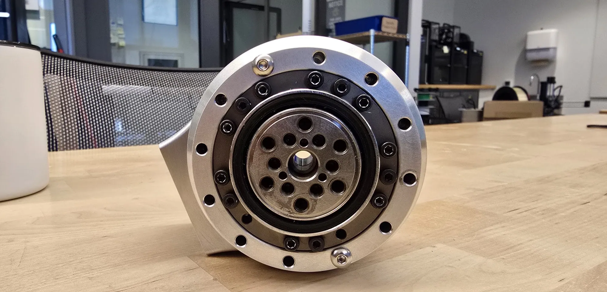
The reducer seated, and the printed housing that lets the motor change.
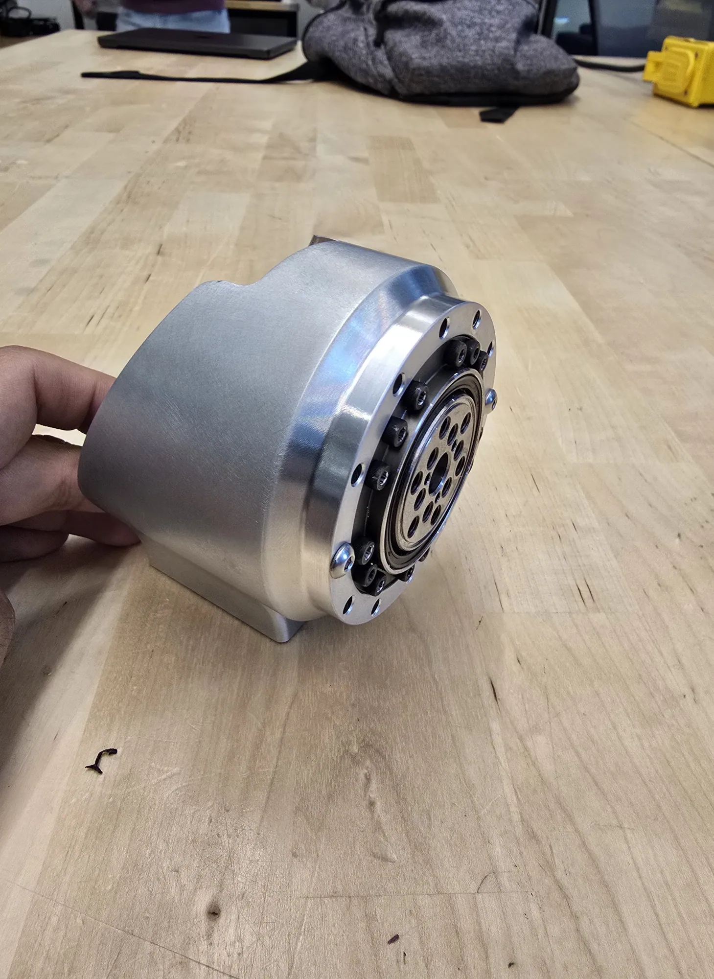
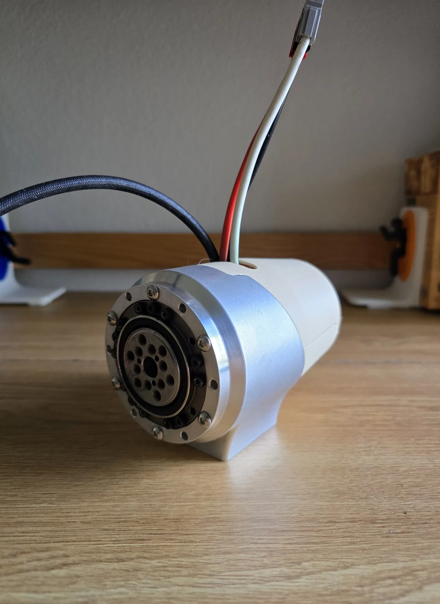
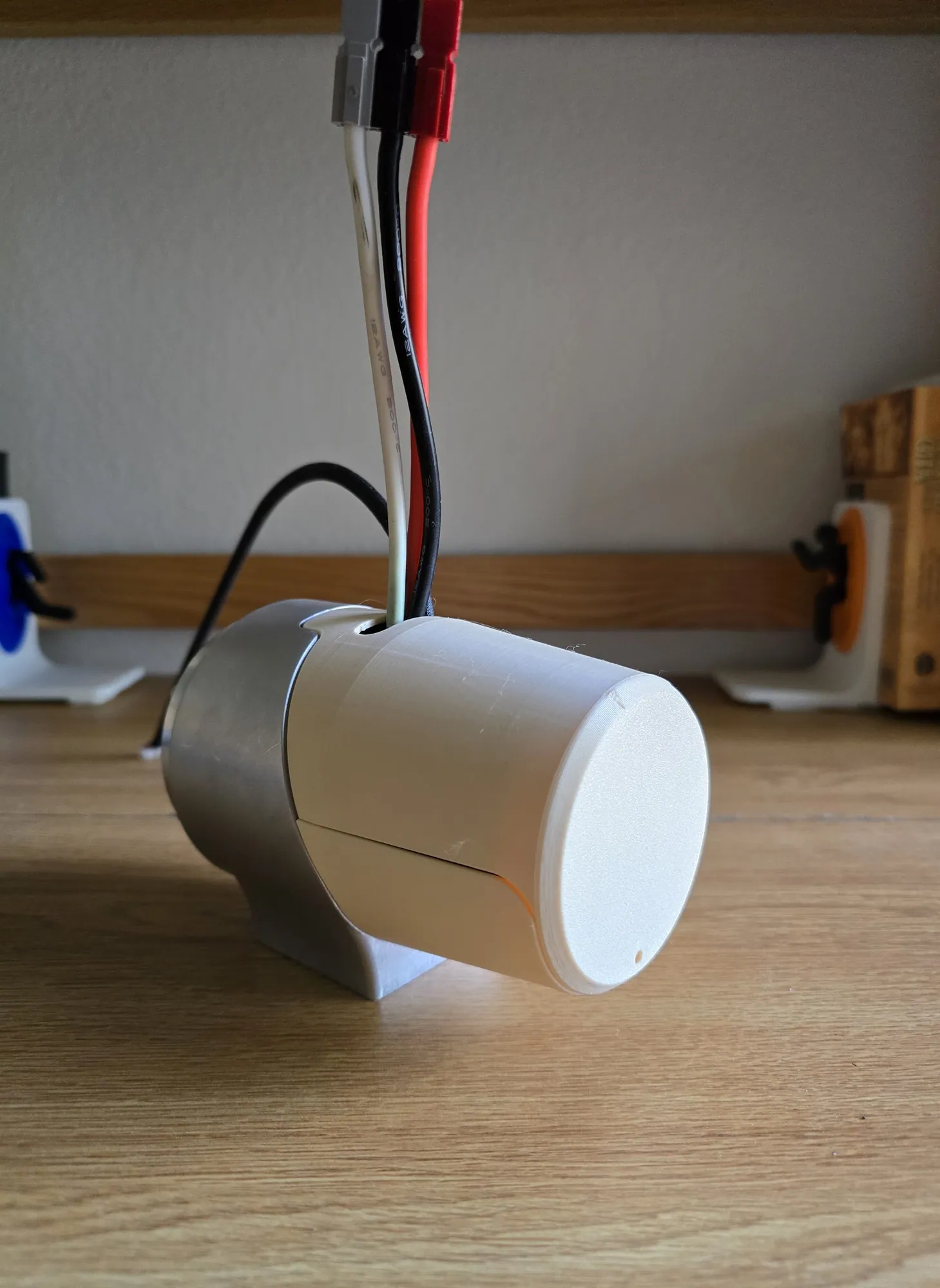
Module assembled
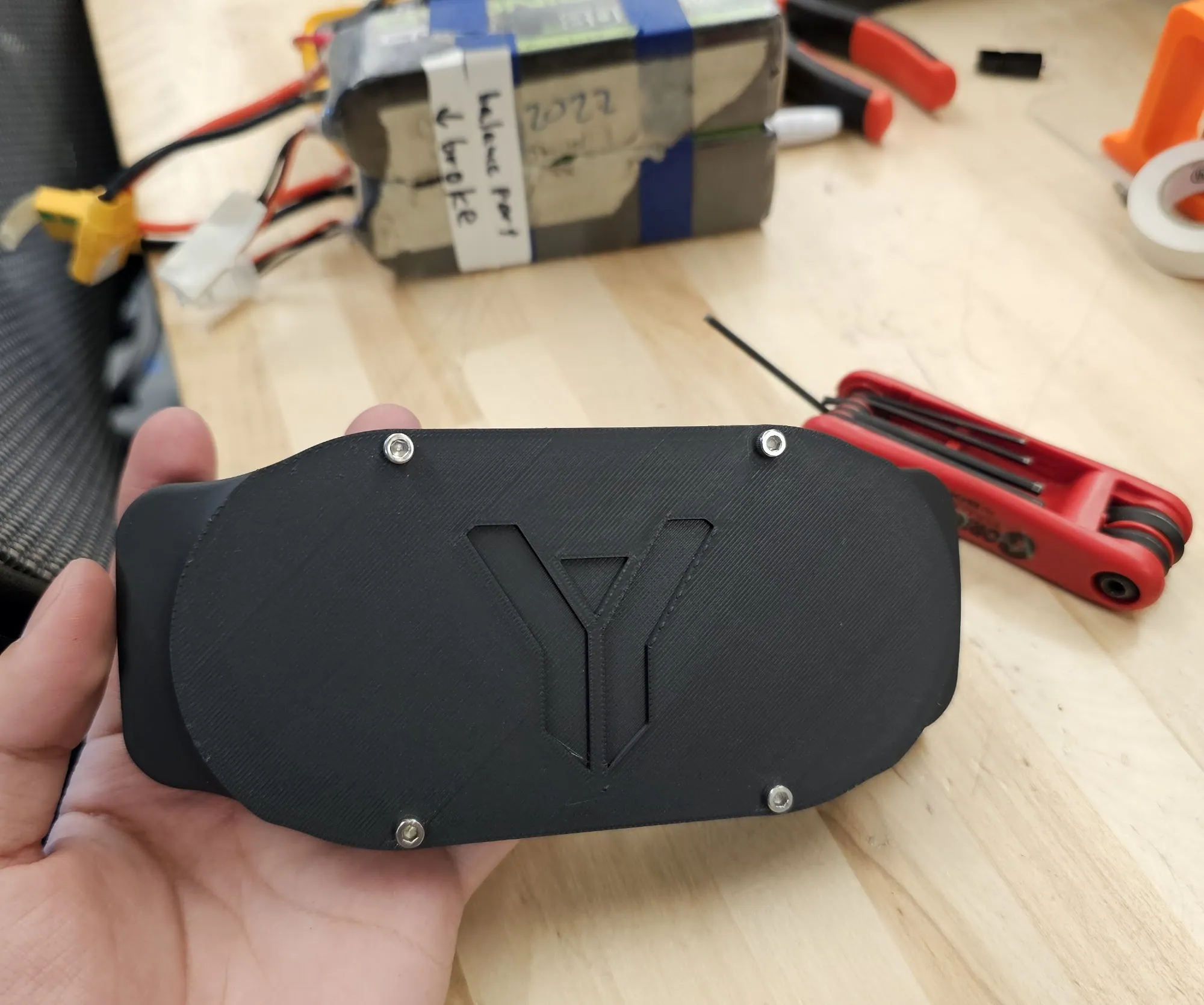
Both ends, on the bench and on the arm.
Controller and fuse board
The electronics the module carries. On the ARM 2.0 retrofit they sat in the forearm box.
Safe Sentinel