
Yonder Robotics · 2025–2026
ARM 2.0
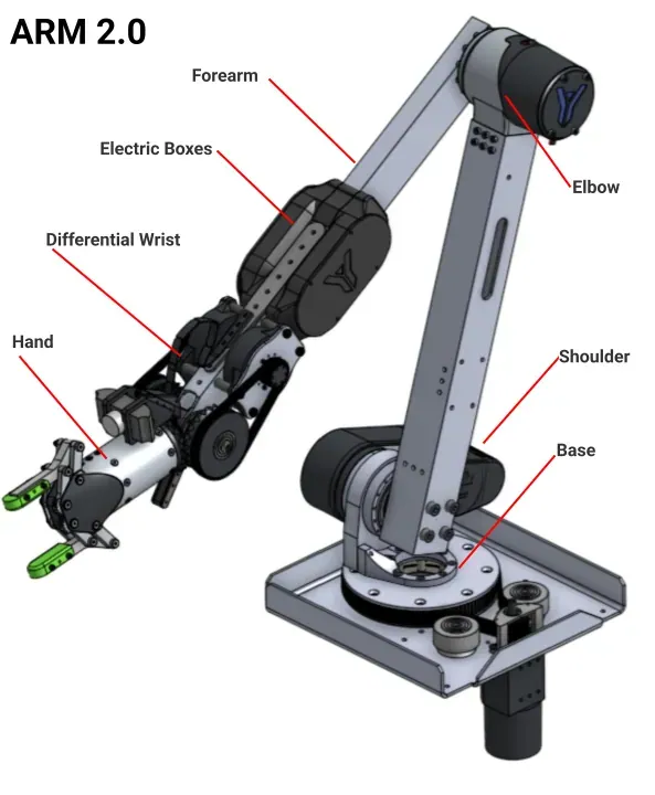
The manipulator Yonder Robotics fielded at the University Rover Challenge. Counting out from the rover deck it is seven pieces (base, shoulder, elbow, forearm, electrical boxes, differential wrist, hand), and I engineered five of them, designed the compact hypoid bevel gear that drives the wrist, and made the parts on 3-axis CNC, manual mills, waterjet, laser, and FDM.
The arm, and my part of it
ARM 2.0 is the manipulator Yonder Robotics fielded at the University Rover Challenge. Counting outward from the rover deck, it is seven named pieces: a base, a shoulder, an elbow, a forearm, the electrical boxes riding on it, a differential wrist, and a hand.
Five of those are mine. The base and the shoulder belonged to other people on the team; everything from the elbow out I engineered, manufactured, and put on the rover.
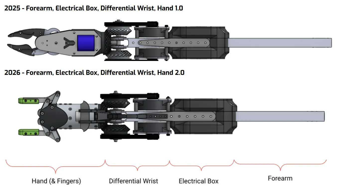
Season over season the elbow, forearm, electrical boxes, and differential wrist carried forward. The end effector is what changed: 2025 ran Hand 1.0, 2026 ran Hand 2.0, on the same wrist interface.
- Base: the rotating deck mount the whole arm stands on. Another member's subsystem.
- Shoulder: the first powered axis, carrying the upper link out to the elbow. Another member's subsystem.
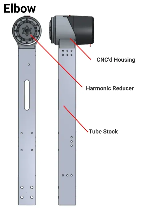
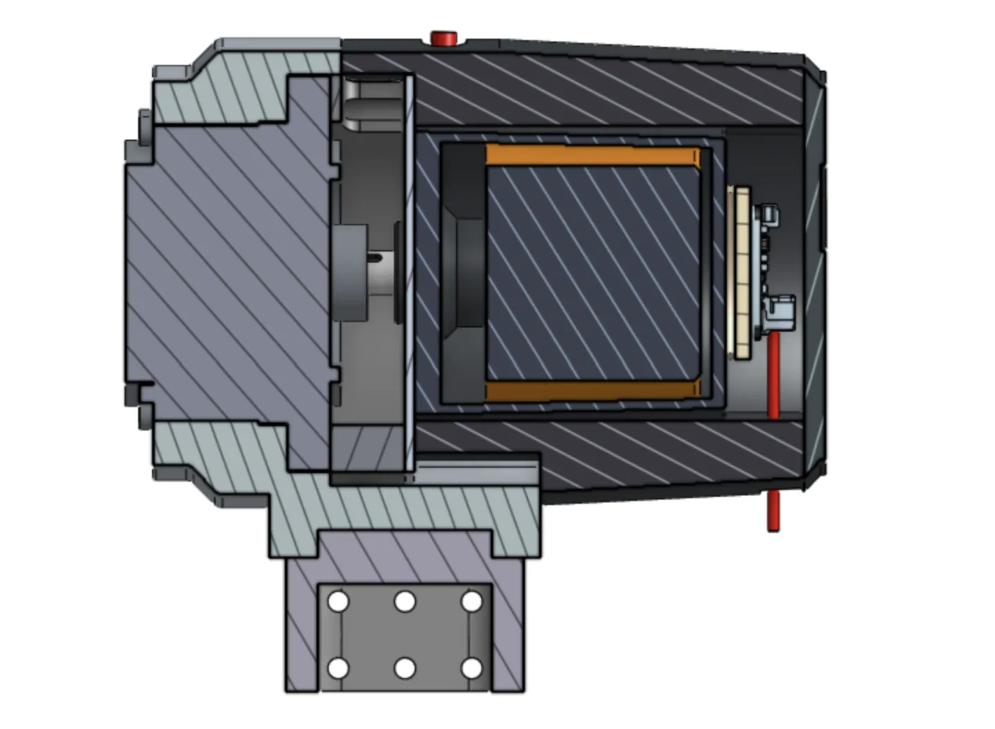
- Elbow: mine. A NEO 1.1 brushless motor through a Harmonic Drive 71-100-118879-11 at 100:1, 110 Nm rated, ODrive controlled, in a machined 6061 housing. Built as the MVP for ARM 3.0's motor module.
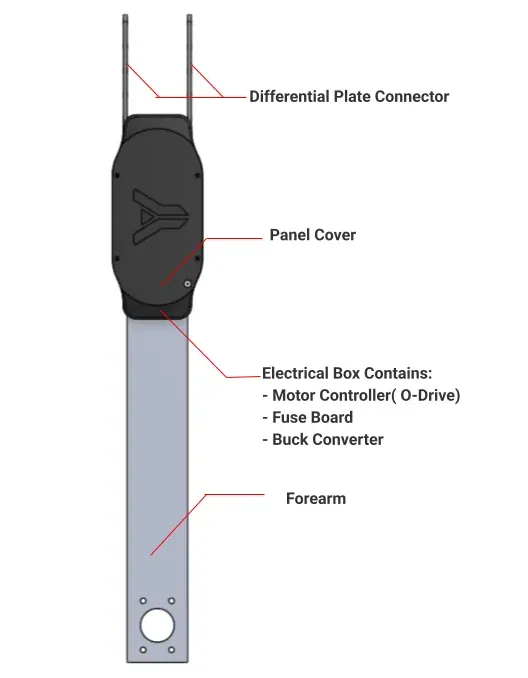
- Forearm: mine. The 6061 tube link between the elbow and the wrist, carrying the electrical boxes and landing the wrist's differential plates at its far end.
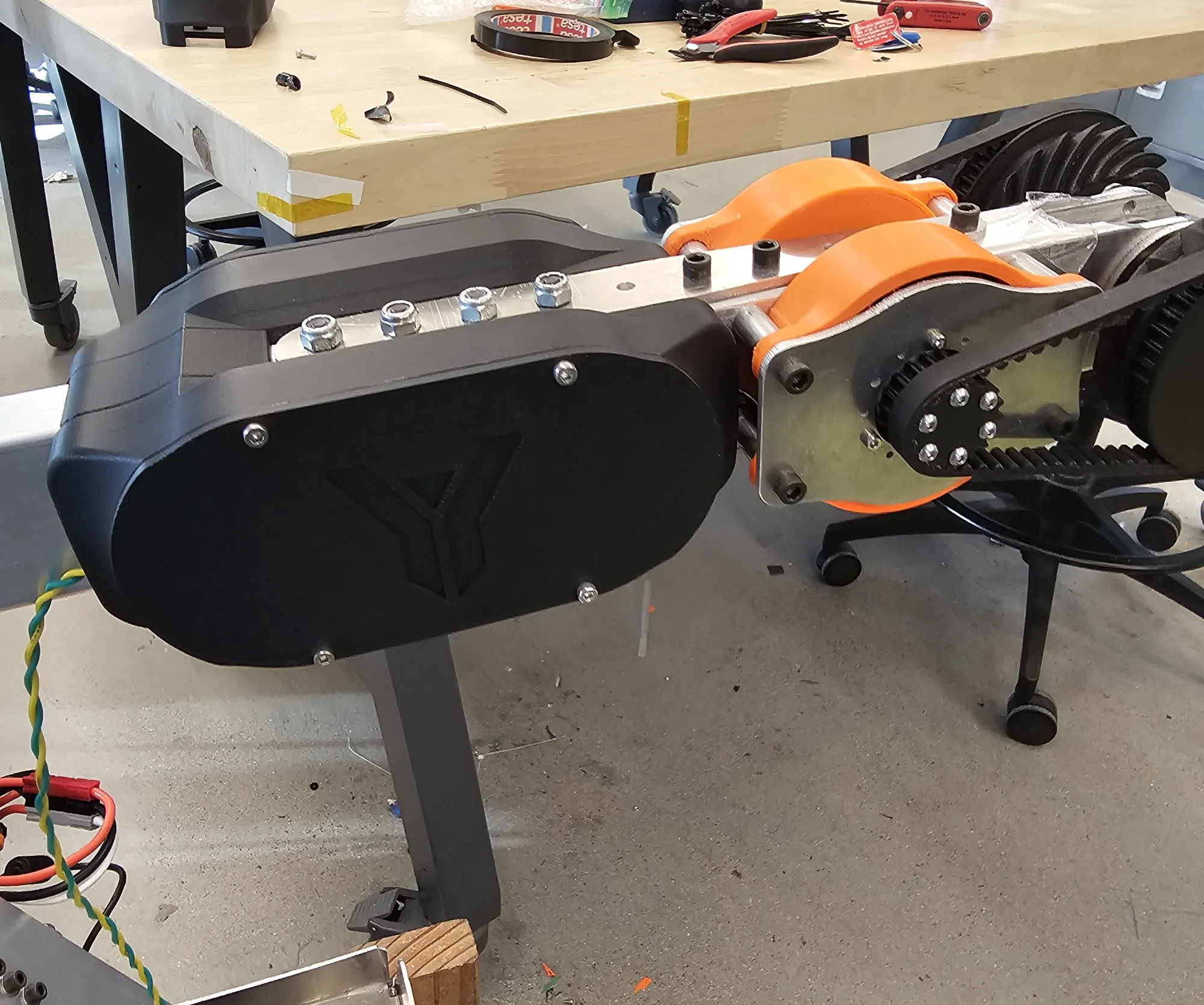
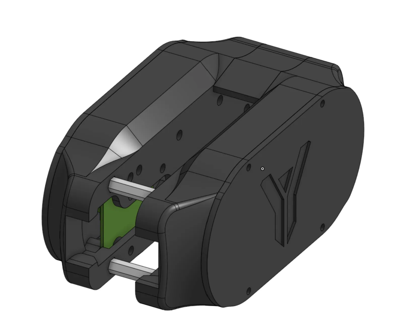
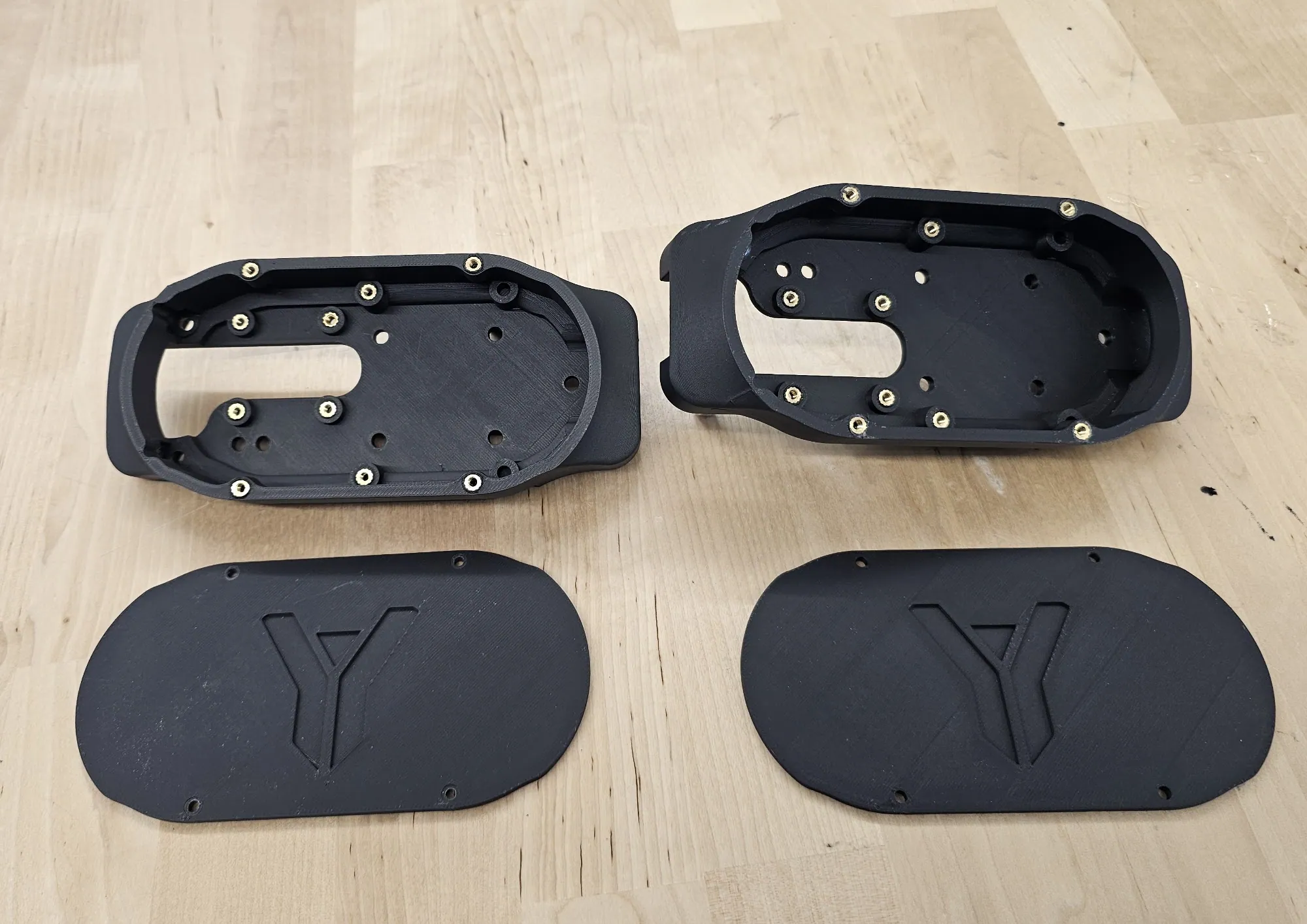
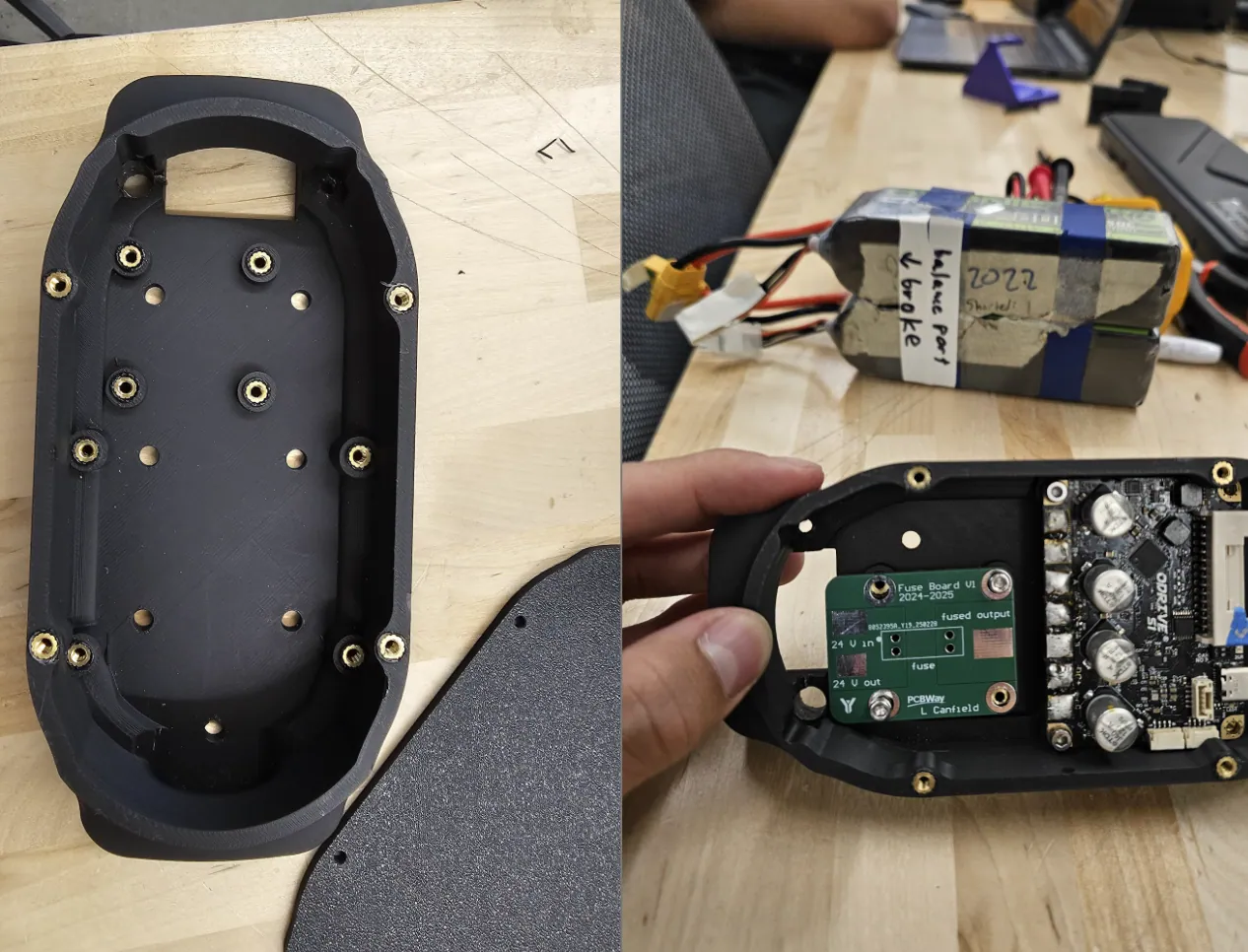
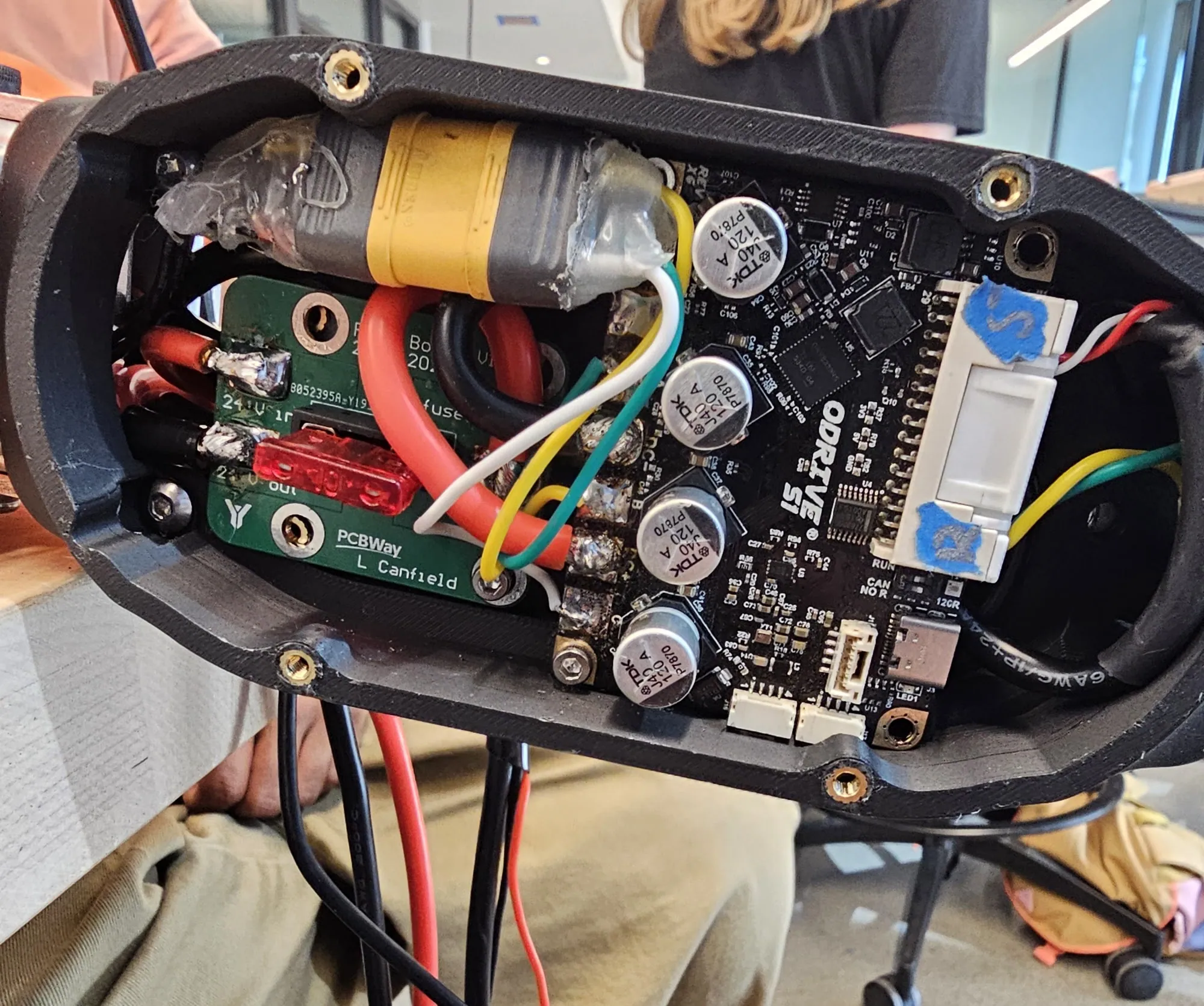
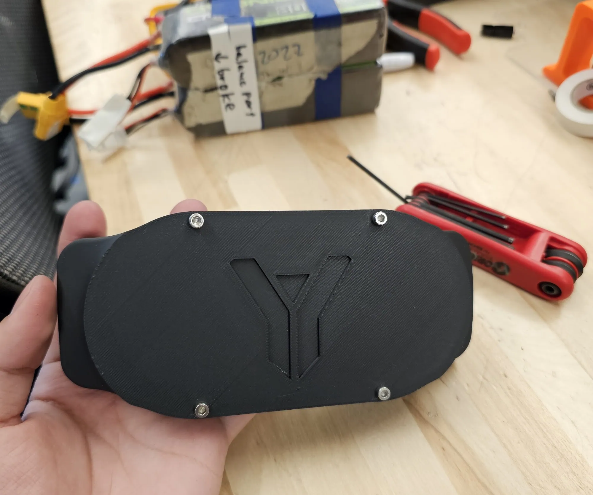
- Electrical boxes: mine. Printed enclosures holding the ODrive, the fuse board, and a 24→12 V buck converter, sealed with M3 screws into heat-set inserts and opened from the back without desoldering.
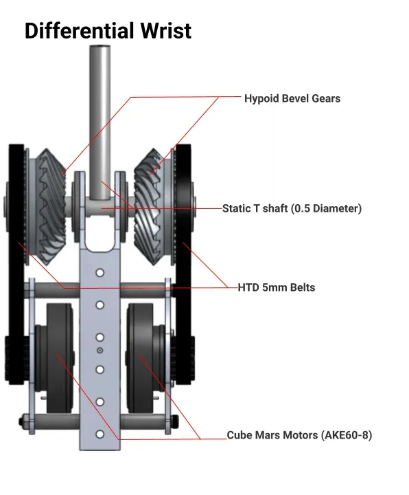
- Differential wrist: mine. Pitch and roll from two CubeMars AKE60-8 outrunners through 2:1 HTD 5 mm belts into custom hypoid bevel gears, on a static 0.5 in T-shaft.
- Hand: mine, twice. Hand 1.0 is a servo-actuated clamp on a slip-ring stem; Hand 2.0 is a four-bar parallel gripper at 181 N that detaches from its stem as a module.
Elbow
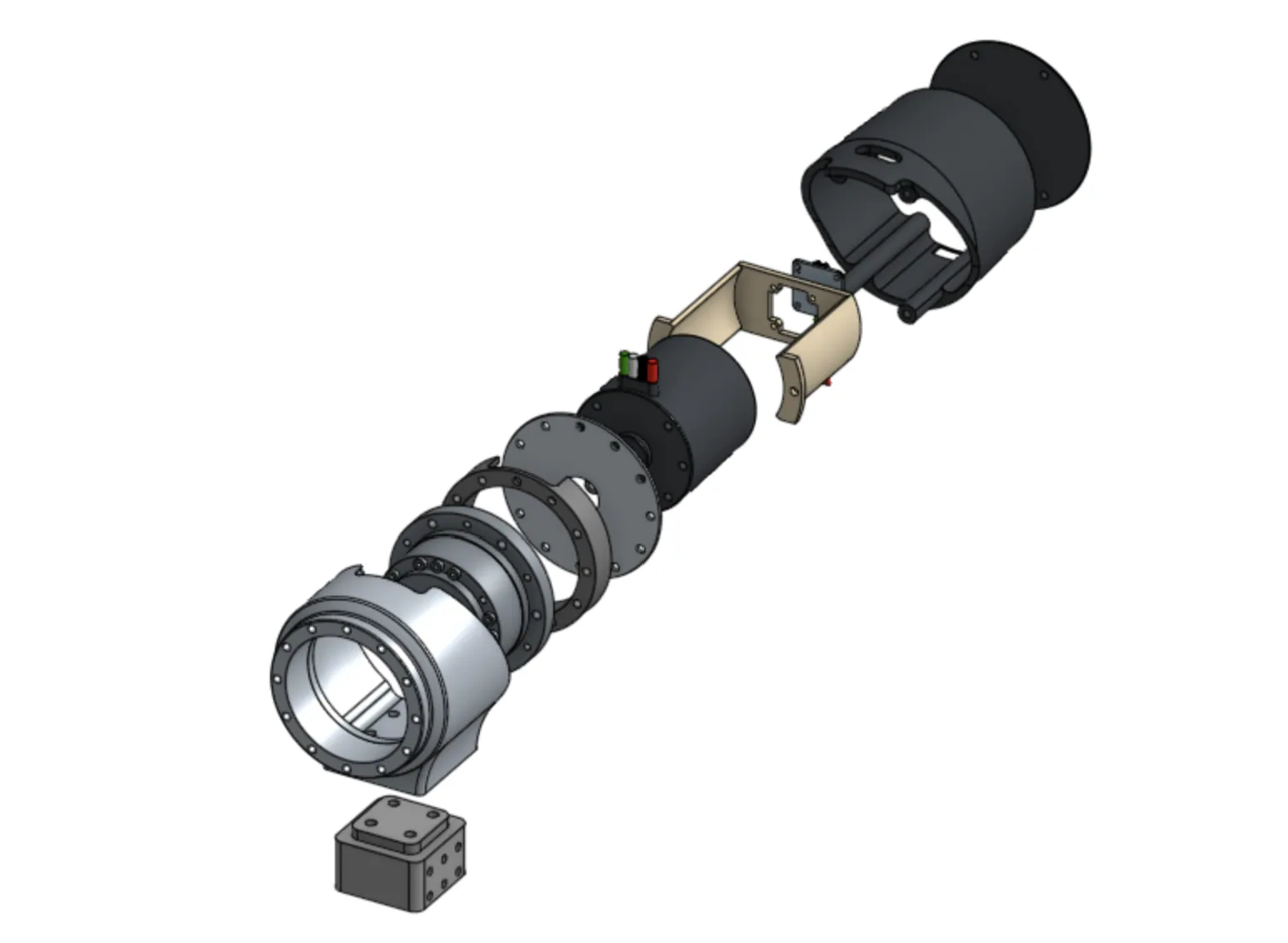
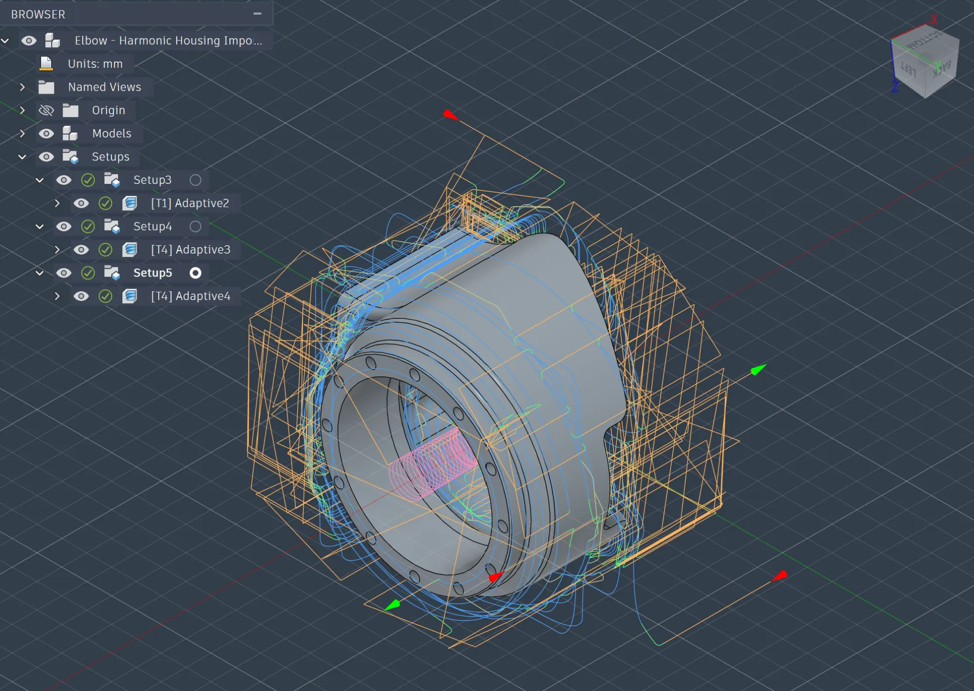
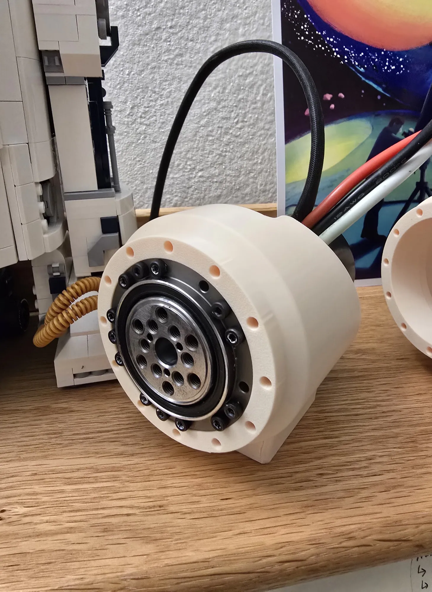
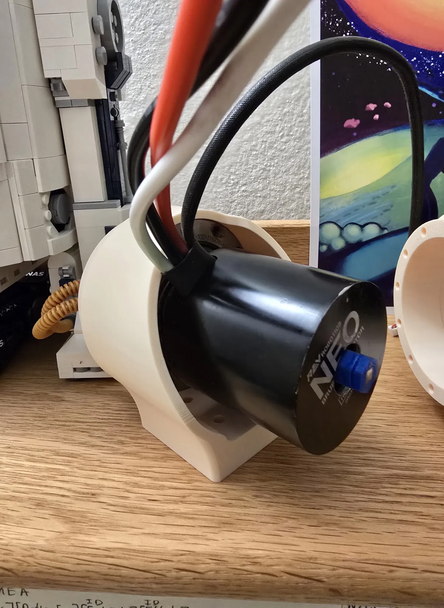
A compact motor module: a NEO 1.1 brushless motor and a Harmonic Drive 71-100-118879-11 at 100:1, 110 Nm rated, run by an ODrive, with the housing and surrounding structure machined from 6061 aluminum.
It exists as much to be costed as to be used. The elbow was the Master Validation Plan for ARM 3.0's fully modular joints: one module, manufactured for real, to establish true manufacturing cost, assembly complexity, and functional performance before committing an arm's worth to contract manufacturing.
Tolerance, manufacturability, and integration risk all surfaced here, while a fix still cost one part instead of six.
Forearm and electrical boxes
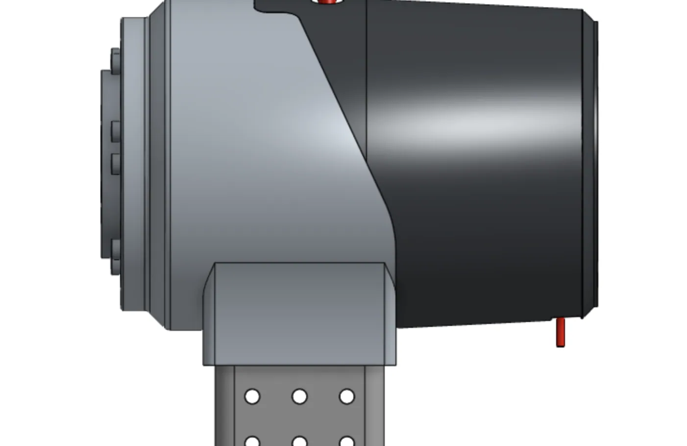
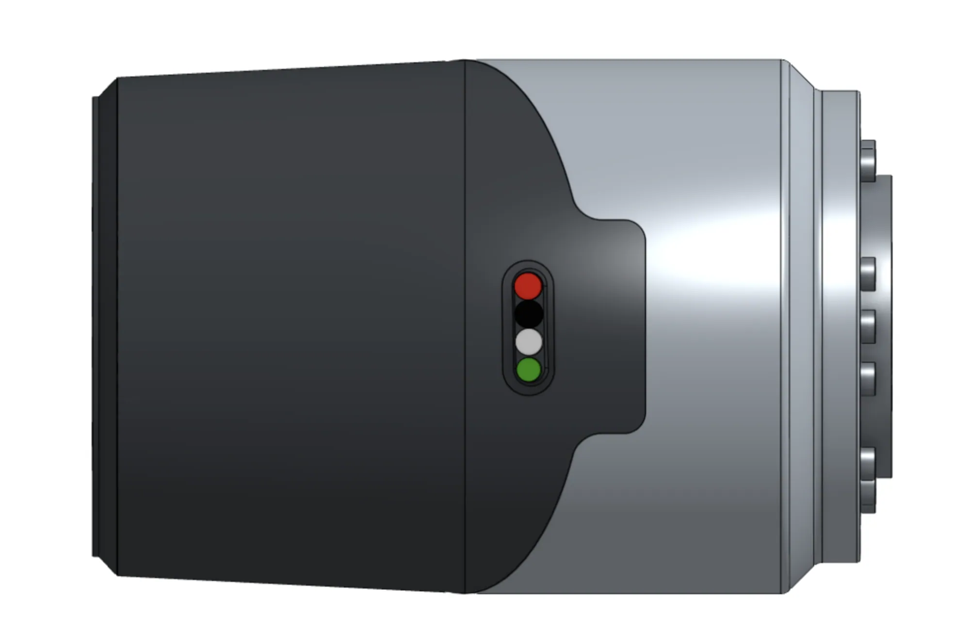
A straightforward subsystem with a clear brief: clean electrical organisation, protection, and ease of use. The electrical team wanted the AKE60-8 motor electronics housed rather than open-mounted, so I laid the enclosures out in Onshape around imported models of the actual boards.
Side panels fasten with M3 screws into heat-set inserts, which is what keeps desert sand and dust out. The shell curves are taken off the wrist's motor plates so the two read as one assembly. A rectangular cutout in the back lets the fuse board and ODrive slide out without desoldering, routing holes carry the wiring, and the right-hand enclosure has an extra compartment for the buck converter.
Everything prints in matte black PLA on an FDM machine, so a revision costs a night rather than a week. Installing it means sliding the electronics in through the back cutout, routing wires through the base and sides, and closing the lid panels: fast deployment, no resoldering, which is what a pit stop with a clock running actually needs.
Differential wrist
A compact, high-torque dual-axis joint giving the arm pitch and roll. Two CubeMars AKE60-8 outrunners, 5 Nm continuous each, drive 2:1 HTD 5 mm belt reductions into custom hypoid bevel gears. Both gears turning together gives pitch; opposed or at different speeds gives roll. Feedback comes from embedded ODrive magnetic encoders on dual ODrive controllers.
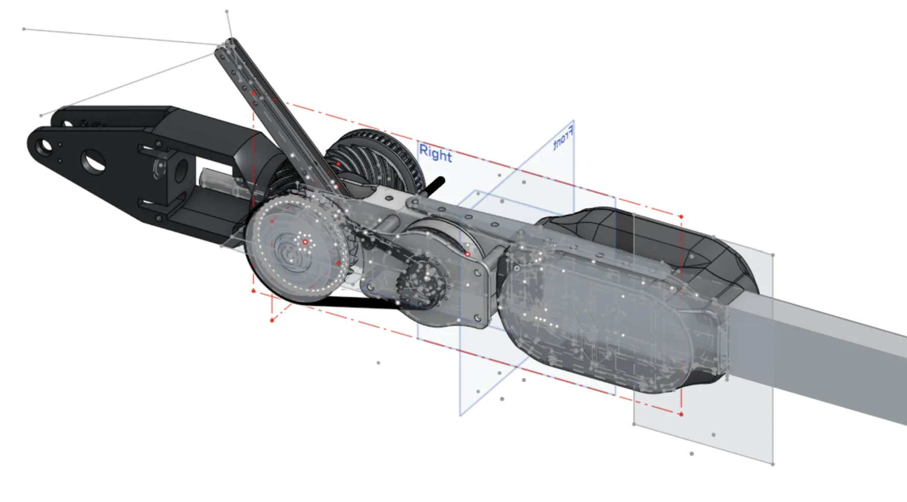
It took three virtual iterations. The original yaw-linkage layout got scrapped in favour of something modular and self-contained that could be pulled and serviced without touching the rest of the rover. The structure is CNC-milled 1×2 in aluminum tube stock with the encoders embedded in it; the motors sit on laser-cut 1/8 in aluminum plates spaced by 1.1 in standoffs.
The T-shaft is two 0.5 in shafts lathed, tapped, and milled flat where they meet. Each bevel gear spins on its own pair of 0.5 in ID bearings, and two more constrain the shaft in the tube. It carries the same 5 kg the rest of the arm is sized for, and it is the interface both hands bolt to.
The hypoid bevel gear
Hypoid rather than straight bevel because a hypoid holds three planes of contact where a straight bevel holds one. Spreading the load that way takes far more shear, which is what makes a printed gear viable at all, and it costs less backlash. The spiral pitch pattern is only manufacturable because the part is printed.
I drew the gears with a custom FeatureScript in Onshape for direct control over the spiral geometry and the offset, then boolean-merged that body into a second FeatureScript that generated the HTD 5 mm belt profile on the same part. Pulley and gear come out as one monolithic print, in mesh by construction. Tough PLA for the prototypes, CF-Nylon on a Markforged for the parts that ran.
A MATLAB script checked contact and bending stress against the AGMA equations, with dynamic loading, material properties, load distribution, and gear geometry as inputs, and size, crown, curvature, and reliability modifiers applied. Geometry factors came off the AGMA spiral bevel charts. Each gear is rated 30 Nm and held a factor of safety of 3.0, which is what justified moving from PLA prototypes to CF-Nylon production parts.
Hand 1.0
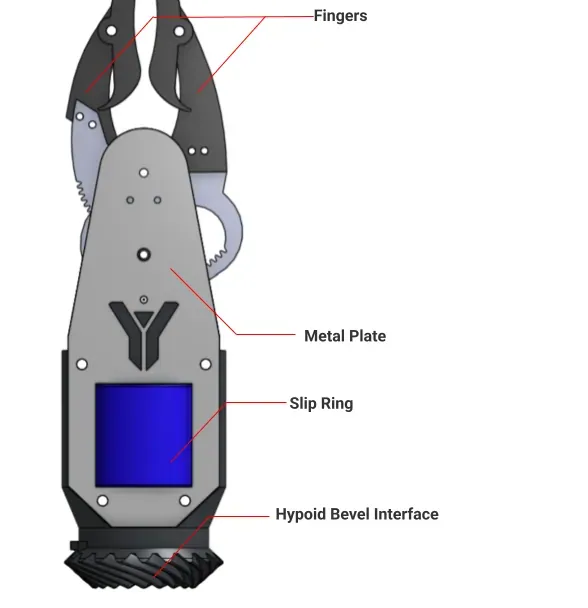
Designed and fabricated in two weeks in spring quarter, straight after the wrist. A servo-actuated clamping mechanism on a 3D-printed body reinforced with aluminum plates, modular enough that a damaged part comes off instead of the whole hand.
Torque and size at the wrist capped it at 0.3 m long. A through-bore slip ring is what bought the length back: the shaft runs long through the hand without the hand itself getting longer, and the wiring passes through a milled 1/4 in slit in the 0.5 in dead-axle shaft, so nothing winds up when the hand rotates continuously. The fingers and servos are legacy Yonder hardware, reused deliberately to save time the schedule did not have.
The body prints in black matte PLA and is reinforced with 1/16 in aluminum plates set perpendicular to the print layers, a quasi-composite that stiffens the weak axis. Plates were cut on a FabLight metal laser; heat-set inserts and press-fit brass bushings carry the fasteners and the pivots. It hangs off the wrist's hypoid bevel interface on a single fastener, so it comes off in one turn.
 22
22Hand 2.0
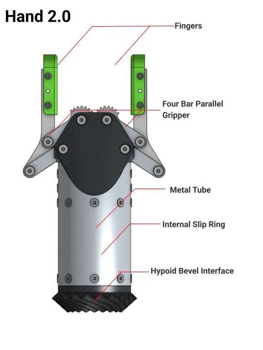
The 2026 end effector: a servo-actuated parallel gripper with infinite wrist rotation built into it. Two DFRobot 45 kg·cm servos drive dual parallel four-bar linkages through gear reduction, so the fingers stay synchronised and parallel through the whole stroke, closing at 181 N, a factor of safety of 3.5 on the 5 kg requirement.
What changed from Hand 1.0 is where the seams are. The gripper is mechanically independent of the stem: it comes off and gets swapped without redesigning the stem, so a future team can hang a different end effector on the same wrist interface, and the fingers are interchangeable on top of that. Rotation, structure, and gripping are three separable subsystems now instead of one part doing all three.
Fingers and linkages are waterjet 1/4 in 5052 aluminum, sandblasted and brushed for low-friction bearing faces; the servo drive gears use stamped fine-pitch teeth. The stem's slip-ring housing is 2.5 in × 1/16 in 6061 tube, machined by hand off a custom radial marking jig. Everything else prints in glass-filled ABS on a Bambu P1S with a hardened nozzle. Joints pivot on M5 shoulder bolts with precision spacers, so metal carries the load and plastic carries the mounting geometry.
 06
06Field
The arm mounted to the rover and ran on soil, on the clock, in front of judges. Everything above was serviceable with the tools in the pit box, because it had to be.
Gallery
Arm assembly
The same forearm, box, and wrist, one season apart.


Elbow
The MVP module: render, section, exploded, toolpath, and the parts that came off it.
Forearm and electrical boxes
Printed shells, heat-set inserts, electronics in, unit closed.
Yonder Robotics